
Related Manuals for RadiSys PL35Q


Summary of Contents for RadiSys PL35Q
- Page 1 PROCELERANT™ ENDURA Q35 MOTHERBOARD PRODUCT MANUAL PL35Q www.radisys.com 007-03198-0000 • December 2007...
- Page 2 Portions of this manual are copyrighted by the PCI Industrial Computer Manufacturers Group, and are reprinted with permission. RadiSys is a registered trademark and Procelerant is a trademark of RadiSys Corporation. Intel and Celeron are registered trademarks and Intel Core is a trademark of Intel Corporation. Microsoft, Windows, and Windows XP are registered trademarks of Microsoft Corporation.
-
Page 3: Table Of Contents
TABLE OF CONTENTS About this manual ............................Safety notices..............................Electrostatic discharge ............................Lithium cell battery..............................Where to get more product information....................Chapter 1: Product Overview ................Product codes ..............................Board layout..............................Chapter 2: Product Specification ................. 11 Mechanical specifications..........................Motherboard ................................I/O shield.................................. - Page 4 Chipset................................Graphics and Memory Controller Hub......................I/O Controller Hub ..............................Video.................................. System memory allocation........................... PCI Express graphics .............................. VGA.................................... Dual DVI MEC ................................. DVI-D..................................S-Video..................................Audio ................................. Network................................I/O ..................................SATA ..................................UART..................................USB .................................... PS/2 mouse and keyboard........................... Super I/O.................................. Expansion interfaces............................
- Page 5 Appendix A: Connector Description ..............41 Onboard connector part numbers......................Jumper settings ............................... Speaker (J9)................................CMOS clear (JRTC1) .............................. PCI slots to system management bus speeds (JI2C1)................... PCI Express slots to system management bus speeds (JI2C2) ..............Watch dog (JWD)..............................Audio (JP5) ................................
-
Page 7: About This Manual
Dispose of the spent battery promptly. Do not recharge, disassemble, or incinerate the battery. Keep the battery away from children. Where to get more product information For additional product information, visit the motherboard product pages on the RadiSys Web site www.radisys.com for access to datasheets, product documentation, BIOS releases, and... -
Page 9: Chapter 1: Product Overview
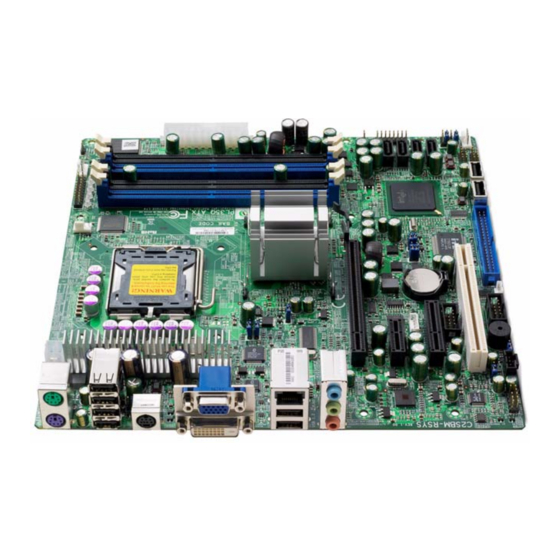
IOSHLD-PL PLVDS03-0-0 ICH9 VGA, S-Video, DVI IOSHLD-PL Note: Processors and memory modules are not included with product codes ending in -0-0. Board layout Figure 1. PL35Q board layout: rear I/O panel Line In Mouse Line Out Microphone Keyboard PS/2 4 USB... - Page 10 Product Overview Figure 2. PL35Q board layout: top view GPIO CTRL FAN2 KEYBOARD/ MOUSE FAN1: 4-PIN POWER 2, 3, 4, 5 JPUSB1 S-VIDEO (OPT) 24-PIN ATX POWER INTEL® USB 0, 1 Q35 EXPRESS CHIPSET AUDIO SLOT 7 PCI-E x16 SLOT 6 PCI-E x1...
-
Page 11: Chapter 2: Product Specification
PRODUCT SPECIFICATION Mechanical specifications Motherboard Figure 3. PL35Q board dimensions 3.15 1.800 [80.01] [45.72] 6.50 [165.10] 5.200 6.100 [132.08] [154.94] 0.00 2.850 [72.39] 3.00 [76.20] 6.200 3.15 6.450 0.00 [157.48] [80.01] [163.83]... -
Page 12: I/O Shield
Product Specification I/O shield Figure 4. I/O shield for the PL35Q motherboard 28.50 23.32 29.63 20.88 21.74 21.13 17.50 12.63 12.32 6.50 6.50 5.00 4.13 3.81 6.59 0.00 MB ZERO-POINT MOUNTING HOLE MB MOUNTING HOLES Thermal specifications When designing a custom thermal solution, it is helpful to know the Q35 motherboard thermal... - Page 13 Electrical specifications Test configuration Component Description Code name: E6400 Part #: HH80557PH0462M Speed: 2.13 GHz FSB: 1066 MHz Quantity: 1 Memory Manufacturer: ATP Part #: AJ28K72G8BHE7S Type: ECC Speed: DDR2-800 Quantity: 1 Size: 1GB Power supply Manufacturer: Ablecom Model: SP423-1S, Rev 3.1 Max Power: 420 W Max Current: +3.3V: 20A...
- Page 14 Product Specification PL35Q motherboard power consumption These tests were run on a revision 1.01 PL35Q motherboard. Table 2. PL35Q power consumption — DOS (stable) 4-pin 8-pin 20/24-pin main power connector Peripheral (HDD) Consumption (W) Input +12V +12V +12V -12V +3.3V...
- Page 15 — Vdrop Result — PASS PASS PASS PASS PASS — PASS PASS Table 11. PL35Q power leakage — Soft Off (S5) with LAN connected 4-pin 8-pin 20/24-pin main power connector Peripheral (HDD) Consumption (W) Input +12V +12V +12V -12V +3.3V...
-
Page 16: Power Delivery To Expansion Slots
Product Specification Table 12. PL35Q power leakage — Soft Off (S5) without LAN connected 4-pin 8-pin 20/24-pin main power connector Peripheral (HDD) Consumption (W) Input +12V +12V +12V -12V +3.3V +12V STBY Voltage (V) 119.20 0.00 0.00 0.00 0.00 0.00 5.08... -
Page 17: Power Budget
A sample power budget for the Q35 motherboards populated with processor, memory, expansion cards, etc. are shown below. Note: These sample values may not apply to to your system. Table 14. Power budget for PL35Q Motherboard current Component Power consumption +3.3V... -
Page 18: Compliance
Product Specification Compliance EMC compliance When correctly installed in a suitable chassis, Q35 motherboards meet these EMC regulations. Table 16. EMC compliance State Value Characteristic Operating IEC 1000-4-2/EN61000-4-2 4kV direct contact, performance criteria B 6kV direct contact, performance criteria C 4kV air discharge, performance criteria B 8kV air discharge, performance criteria C Fast transient/burst... -
Page 19: Mtbf Reliability Predictions
MTBF reliability predictions MTBF reliability predictions The predicted MTBF for Q35 motherboards at 35ºC and 55ºC are shown in Table 17. The predictions are based on Telcordia SR-332 Issue 1, Method 1, Case 3 with the following underlying assumptions: 50% default stress ratio for all modeled components Application-specific stress ratios applied for electrolytic capacitors when available Ground benign in a controlled environment Level II quality grade on all components... - Page 20 Product Specification...
-
Page 21: Chapter 3: Hardware Reference
HARDWARE REFERENCE General specifications Table 18. General specifications: PL35Q Item Item Description Physical Dimensions 9.6“ x 9.6“ Form Factor MicroATX revision 2.2 Processor — These processors are supported: Intel Core 2 Duo E8400 Intel Core 2 Duo E6400 Intel Core 2 Duo E4300... - Page 22 Hardware Reference Table 18. General specifications: PL35Q Item Item Description Network — Single Intel Gigabit Ethernet via Intel 82566DM PHY controller Two Ethernet LEDs for Ethernet link and activity indication PXE boot and Wake-On-LAN support One RJ45 Ethernet connector on rear I/O panel Support for12 USB 2.0 ports with a speed of up to 480Mbps: six ports on rear I/O panel, two onboard...
-
Page 23: Block Diagram
Block diagram Block diagram Figure 5. PL35Q block diagram VRM_V11.0 LGA775 processor VRM 11.0 CK505_CLK FSB 1333/1066MHz DIMM_CHA Integrated GMA 3100 graphics controller DRR2_800/667 Intel Q35 chipset PCIE_x16 1 PCIE_x16 graphics interface DIMM_CHB DVI-D, S-Video graphics SATA/300 PCI_32 4 SATA II ports 1 PCI slot USB2.0/1.1... -
Page 24: Power Supply
Hardware Reference Power supply Q35 motherboards support soft-switched and hard-switched ATX power supplies. The standard 24-pin ATX power connector provides +12V, -12V, +5V standby, +5V, +3.3V power rails and an extra 4-pin ATX power connector provides +12V for CPU use only. A 20-pin ATX power connector can also be used. -
Page 25: Processor
Q35 motherboards support Intel Celeron, Pentium Dual-Core, and Core 2 Duo processors in a socketable LGA775 package. For support of other processors, refer to the Procelerant Endura Q35 Supported Processors List on the RadiSys Web site. Table 20. Supported processors Clock... -
Page 26: Memory
The BIOS automatically configures the motherboard for the correct size, speed, and type. For a list of qualified memory modules, refer to the Procelerant Endura Q35 Qualified Memory List on the RadiSys Web site. Chipset Graphics and Memory Controller Hub... -
Page 27: I/O Controller Hub
Chipset I/O Controller Hub The Intel ICH9 and ICH9DO I/O provide extensive I/O support: Direct Media Interface (DMI) support for chip-to-chip connection between the GMCH and PCI Express Base Specification, Revision 1.1 support PCI Local Bus Specification, Revision 2.3 support for 33 MHz PCI operations ACPI Power Management Logic Revision 3.0b support Enhanced DMA controller, interrupt controller, and timer functions Integrated Serial ATA host controllers with independent DMA operation up to six ports and... -
Page 28: Video
The Q35 motherboards support PCI Express graphics acceleration cards via the PCI Express x16 graphics slots. This support includes: One PCI Express x16 graphics slot on the PL35Q motherboard, electrically x16 interface PCI Express frequency of 1.25 GHz resulting in 2.5 Gb/s each direction per lane Raw bit-rate of 2.5Gb/s on each lane while employing 8b/10b encoding to transmit data... -
Page 29: Vga
Video Q35 motherboards provide a standard DA15F VGA connector on the rear I/O panel. The integrated Intel GMA 3100 video controller supports: 350MHz integrated 24-bit RAMDAC Resolution up to 2048x1536 pixels at 75Hz refresh DDC2B Compliant Interface Dual DVI MEC Use this procedure to set up dual DVI monitors using a dual DVI MEC. -
Page 30: Audio
I/O header to hear the beep signals. Network The PL35Q motherboard has a single Gigabit Ethernet controller. Ethernet port 0 uses the Intel 82566DM PHY controller, which connects to the ICH9/ICH9DO LAN (the MAC integrated on the ICH9/ICH9DO chipset) through a dedicated interconnect. -
Page 31: I/O
SATA The PL35Q motherboards provide four SATA headers to attach SATA disk drives via the SATA controller on the ICH9/ICH9DO chipset. The blue SATA connector supports eSATA for use with external devices at a distance of up to 2m. Note: SATA interface transfer rates are independent of Ultra DMA mode settings in the BIOS setup utility. -
Page 32: Ps/2 Mouse And Keyboard
PCI slots are compliant with the PCI Local Bus Specification Version 2.3. The PL35Q motherboard has one 32-bit, 33MHz, 3.3V PCI slot. PCI Express All PCI Express interfaces on the PL35Q motherboard are compliant with the PCI Express Base Specification Version 1.1. One PCI Express x16 graphics interface One PCI Express x4 interface One PCI Express x1 interface. -
Page 33: Cmos Ram And Rtc
CMOS RAM and RTC CMOS RAM and RTC The chipset integrates real-time clock (RTC) and 256 bytes of CMOS RAM that is used by the BIOS to store configuration information. A replaceable lithium cell battery (type CR2032) backs up both the RTC and the CMOS RAM, and provides approximately 5 years of un-powered backup. -
Page 34: Power Management
Hardware Reference Power management ACPI power states Table 22 shows the Advanced Configuration and Power Interface (ACPI) 3.0 power states that the Q35 motherboards support. Table 22. Supported ACPI power states VCC state Supported ACPI states 12V/-12V/5V/3.3V 5V standby G0/S0 G1/S3 G1/S4 G2/S5... -
Page 35: System Management
System management System management The Q35 motherboard includes hardware system management functions using the Winbond W83627DHG chipset. These functions include monitoring system voltages, monitoring temperatures, and monitoring and controlling the system fan. Voltage monitoring Table 23 identifies the motherboard voltage rails that are monitored and explains how they are used. -
Page 36: Fan Control
Hardware Reference Fan control The Q35 motherboards support three fan monitors that check the fan tachometer signals to determine the fan’s rotational speed. The three monitors are assigned to the processor fan, system fan 1, and system fan 2. Fan speed modes are controlled in the BIOS setup utility, Advanced Features > Hardware Monitor menu. -
Page 37: Hard Disk Led
Front panel connections and indicators Hard disk LED To indicate disk activity on any of the SATA or ATA channels, connect a single-color LED between pins 13 (anode) and 14. Overheat/fan failure LED To indicate an overheat of the CPU or a fan failure, connect a single-color LED between pins 7 (anode) and 8. - Page 38 Hardware Reference...
-
Page 39: Chapter 4: Bios Configuration And Os Support
BIOS CONFIGURATION AND OS SUPPORT BIOS overview The Q35 system BIOS uses the Phoenix TrustedCore BIOS with RadiSys extensions. BIOS features include: Core multi-processing for Intel Core 2 Duo and Pentium Dual-Core processors ACPI 3.0 wake up from S3, S4, and S5... -
Page 40: Bios Setup
For detailed instructions on BIOS configuration, refer to the Procelerant Endura Q35 BIOS Setup Utility Specification. Update and recovery BIOS release packages are periodically available on the RadiSys Web site to address known issues or to add new features. The release packages include detailed instructions for updating the BIOS. -
Page 41: Appendix A: Connector Description
CONNECTOR DESCRIPTION Onboard connector part numbers Table 25. Onboard connector part numbers Onboard connector Part number Description CD-ROM header HDR-012L CNT, box/header, 1*4, DIP/2.54/M/ 11.4*12.75, black, BRASS/PBT, protect.PBF ATX power connector, 4-pin SKT-092L CNT,power-conn,2*2pin,DIP/M/3,5A/ 250V,BRASS/LCP,With post,half transpare,Au:15u-in ATX power connector, 24-pin SKT-110 CNT, power-conn, 2*12pin, DIP/M/4.2,1A, half transpare, BRASS/NYLON66,with post... -
Page 42: Jumper Settings
Connector Description Table 25. Onboard connector part numbers Onboard connector Part number Description Rear I/O panel — Triple audio JA33331-H11P-4F HD audio phone jack vertical 1X3 port,Pb- jacks Free (JA33331-H11P-4F) Rear I/O panel — RJ45 Gigabit SKT-0262L CNT,RJ45/dual USB,P35-152-19W9,Pb-Free Ethernet port Rear I/O panel —USB ports SKT-0135L CNT, I/o-conn, usb*4/16pin, DIP/M/2, black,... -
Page 43: Pci Express Slots To System Management Bus Speeds (Ji2C2)
Jumper settings PCI Express slots to system management bus speeds (JI Setting Definition Jumpered Enabled No jumper Disabled (default) This jumper allows you to connect PCI/PCI-Express slots to the System Management Bus. The default setting is open to disable the connection. USB wake-up (JPUSB1/JPUSB2) Setting Definition... -
Page 44: Audio (Jp5)
Connector Description Audio (JP5) Setting Definition Pins 1-2 jumpered Enabled (default) Pins 2-3 jumpered Disabled Gigabit LAN (JPL1, JPL2) Setting Definition Pins 1-2 jumpered GLAN enabled (default) Pins 2-3 jumpered GLAN disabled The JPL jumpers enable or disable Gigabit LAN ports 1 and 2 on the motherboard. ITE IDE (JP2) Setting Definition... -
Page 45: Internal Device Connectors
Internal device connectors Internal device connectors Pin #1 of most internal connectors and headers are marked with an asterisk (*) on the PCB of Q35 motherboards. ATX power connector (24-pin, 12V)) Pin # Signal Pin # Signal +3.3V +3.3V +3.3V -12V PS_ON# Power_GOOD... -
Page 46: Clear Cmos Jumper
Connector Description Clear CMOS jumper Jumper setting Configuration Pins 1 &2 jumpered (default) Normal operation Pins 2 & 3 jumpered Clear CMOS Fan header Pin # Signal Pin # Signal +12V Tachometer FAN_PWM Front panel I/O header PIN# Description PIN# Description Wiring Notes Power LED LED_Anode+... -
Page 47: Ide Connector
Internal device connectors IDE connector Pin # Signal Pin # Signal Reset# DD10 DD11 DD12 DD13 DD14 DD15 Key pin DMARQ DIOW# DIOR# IORDY CSEL DMACK# INTRQ Reserved PDIAG# CS0# CS1# DASP#... -
Page 48: Pci Express X1 Slot
Connector Description PCI Express x1 slot Note: The signals for hot plug presence detection in the table below are not supported on Q35 motherboards. Side B Side A Pin # Signal Description Signal Description +12V 12V power PRSNT1# Hot plug presence detect +12V 12V power +12V... -
Page 49: Pci Express X4 Slot
Internal device connectors PCI Express x4 slot The signals for hot plug presence detectoin in the table below are not supported on Q35 motherboards. Side B Side A Pin # Signal Description Signal Description +12V 12V power PRSNT1# Hot plug presence detect +12V 12V power +12V... -
Page 50: Pci Express X16 Slot
Connector Description PCI Express x16 slot The signals for hot plug presence detectoin in the table below are not supported on Q35 motherboards. Side B Side A Pin # Signal Description Signal Description +12V 12V power PRSNT1# Hot plug presence detect +12V 12V power +12V... - Page 51 Internal device connectors Side B Side A Pin # Signal Description Signal Description PRSNT2# Hot plug presence detect Ground Ground RSVD Reserved End of X4 connector PETp4 Transmitter differential pair Lane 4 RSVD Reserved PETn4 Transmitter differential pair Lane 4 Ground Ground PERp4...
- Page 52 Connector Description Side B Side A Pin # Signal Description Signal Description Ground PERp12 Receiver differential pair Lane 12 Ground PERn12 Receiver differential pair Lane 12 PETp13 Transmitter differential pair Lane 13 Ground PETn13 Transmitter differential pair Lane 13 Ground Ground PERp13 Receiver differential pair Lane 13...
-
Page 53: Pci Slot
Internal device connectors PCI slot Pin # Side B signal Side A signal -12V TRST# +12V INTA# INTB# INTC# INTD# PRSNT1# Reserved Reserved +3.3V (I/O) PRSNT2# Reserved CONNECTOR KEY CONNECTOR KEY Reserved 3.3Vaux RST# +3.3V (I/O) GNT# REQ# +3.3V (I/O) PME# AD[31] AD[30]... - Page 54 Connector Description Pin # Side B signal Side A signal PCIXCAP STOP# LOCK# +3.3V PERR# SMBCLK +3.3V SMBDAT SERR# +3.3V C/BE[1]# AD[15] AD[14] +3.3V AD[13] AD[12] AD[11] AD[10] M66EN AD[09] AD[08] C/BE[0]# AD[07] +3.3V +3.3V AD[06] AD[05] AD[04] AD[03] AD[02] AD[01] AD[00] +3.3V (I/O)
-
Page 55: Sata Header
Internal device connectors SATA header Pin # Signal Pin # Signal SATA_TXP SATA_TXN SATA_RXN SATA_RXP {Omitted} SMBus header Pin # Signal Pin # Signal +3.3V_STANDBY SMB_DATA SMB_CLK UART port (internal) Pin # Signal Pin # Signal USB header (internal) Pin # Signal Pin # Signal... -
Page 56: External Device Connectors
Connector Description External Device Connectors Audio jacks (triple, build option) Port Configuration Blue Line in Green Line out Pink Microphone input PS/2 mouse and keyboard Pin # Signal Pin # Signal Data Clock Ground RJ45 Gigabit Ethernet port Pin # Signal Pin # Signal... -
Page 57: Vga Connector
External Device Connectors VGA connector Pin # Signal Pin # Signal GREEN BLUE RED GND GREEN GND BLUE GND +5V (optional) SYNC GND ID1 or SDA HSYNC VSYNC ID3 or SCLK... - Page 58 Connector Description...
-
Page 59: Appendix B: System Resources
SYSTEM RESOURCES I/O map Address (HEX) Description 0000 — 000F DMA controller 1 0020 — 0021 Interrupt controller 1 002E — 002F Super I/O controller 0040 — 0043 Timer controller 004E — 004F TPM controller 0060, 0064 Keyboard controller emulation register (returns zero) 0068, 006C CPLD port 0070 —... -
Page 60: Pci Bus Topology
System resources Address (HEX) Description Dynamically assigned Four USB controllers (32 locations on a 32-byte boundary) Dynamically assigned SMBus controller (16 locations on a 16-byte boundary) Dynamically assigned LAN controller (4096 locations on a 4096-byte boundary) PCI bus topology Physical Device AdSel Ints Intel Q35 (GMCH) -
Page 61: Smbus Resource Allocation
SMBus resource allocation SMBus resource allocation Device Address ICS 9LPRS511 1101001X DIMM 0 Slot 10100000 DIMM 1 Slot 10100010 DIMM 2 Slot 10100100 DIMM 3 Slot 10101000 SIO H/W Monitor 01011010 ISA interrupt allocation Interrupt Function IRQ0 System timer (internal ICH7-M connection) IRQ1 Keyboard controller via SERIRQ IRQ2... -
Page 62: Isa Dma Channel Allocation
System resources ISA DMA channel allocation The motherboard does not have an ISA bus, but uses a faster ISA-compatible DMA controller for compatibility with the AT architecture. DMA channel Description Channel 0 Unassigned 8-bit channel Channel 1 Unassigned 8-bit channel Channel 2 Unassigned 8-bit channel Channel 3... -
Page 63: Post Checkpoint Codes
3. 00 10 00 00 = 1-3-1-1 beeps Note: Only standard Phoenix TrustedCore BIOS POST 80 codes are listed in the tables below. If you encounter other POST 80 codes, contact RadiSys for further assistance. Phoenix TrustedCore BIOS checkpoint codes Checkpoint Code Description IPMI Initialization. - Page 64 System resources Checkpoint Code Description Initializes external cache before memory auto size. Initializes the timers. Tests the DMA registers. Initializes interrupt controllers for some shutdowns. Verifies DRAM refresh. Initializes the Keyboard Controller for Keyboard Test. Sets 4GB segments for DS,ES,FS,GS,SS. Sizes DRAM.
- Page 65 POST checkpoint codes Checkpoint Code Description Performs memory tests on extended RAM. Preforms address tests on extended RAM. Configures MTRR for extended memory caching. Initializes the non-primary processors. Enables cache(s). Initializes SMM, SMRAM and SMI code. Displays cache size. Displays BIOS shadow status. Zeroes un-initialized extended memory with cache on.
- Page 66 System resources Checkpoint Code Description Checks if User has requested to enter setup. Checks to see if setup should be executed. Clears ConfigFailedBit and InPostBit in CMOS. Checks for POST errors. Clears CMOS bits to indicate that POST is complete. Stores enhanced CMOS values in non-volatile area.
- Page 67 POST checkpoint codes Boot block checkpoint codes Description Checkpoint Code 080h Chipset initialization. 081h Bridge initialization. 082h CPU initialization. 083h System timer initialization. 084h System I/O initialization. 085h Checks force recovery boot. 086h Checks BIOS checksum. 087h Enters BIOS. 088h Initializes Multi-Processor if present.
- Page 68 System resources Intel memory initialization checkpoint codes Checkpoint Code Description Detects GMCH device. Progress meter inside routine: DDRProgRCOMP Progress meter inside routine: DDRProgRCOMP Progress meter inside routine: DDRProgRCOMP Progress meter inside routine: DDRProgRCOMP Progress meter inside routine: DDRProgRCOMP Progress meter inside routine: DDRProgRCOMP Progress meter inside routine: DDRProgRCOMP Begin Common Initialization.
-
Page 69: Error Message Codes
POST checkpoint codes Error message codes Once the video is enabled, errors or warnings are sent to the video display as text messages shown in this table. Note: These messages are always displayed unless the board is configured for quiet boot or headless operation. - Page 70 System resources Class Number Name I/O errors 2E0h ERR_IO_ADDRESS 2E1h ERR_IO_COM 2E2h ERR_IO_LPT 2E3h ERR_IO_CONFLICT 2E4h ERR_IO_UNSUPPORTED 2E5h ERR_IO_IRQ 2E6h ERR_IO_IDE 2E7h ERR_IO_FDD 2F0h ERR_OTHER_CPUID 2F1h ERR_OTHER_BIST 2F2h ERR_OTHER_BSP 2F3h ERR_OTHER_AP 2F4h ERR_OTHER_CMOS 2F5h ERR_OTHER_DMA 2F6h ERR_OTHER_NMI 2F7h ERR_OTHER_FAILSAFE...
-
Page 71: Appendix C: Industry Standard References
INDUSTRY STANDARD REFERENCES Architecture Specification Location Form factor ATX Specification Version 2.2 www.formfactors.org/formfactor.asp microATX form factor Processor Intel Core 2 Duo processor www.intel.com/products/processor/core2duo/ index.htm Intel Pentium Dual-Core processor www.intel.com/products/processor/pentium_dual- core/index.htm Intel Celeron processor www.intel.com/products/processor/celeron/ index.htm Chipset Intel Q35 GMCH chipset www.intel.com/products/chipsets/Q35_Q33/ index.htm Intel ICH9/ICH9DO chipset...
Need help?
Do you have a question about the PL35Q and is the answer not in the manual?
Questions and answers