Table of Contents
Advertisement
Advertisement
Table of Contents

Related Manuals for Origen ae S10V


Summary of Contents for Origen ae S10V
- Page 1 S10V S1 4V S1 6V user guide Origen...
- Page 2 S10V S1 4V S1 6V user guide Thank you for purchasing this Origen htpc enclosure. We recommend that you read this user guide thoroughly before installation. Origen has rapidly grown to be one of the worlds leading HTPC enclosure manufacturers since its inception in 2000. We were one of the first companies...
-
Page 3: Table Of Contents
S10V S10V overview Opening the case Optical disk drive installation Hard drive installation Auxiliary access slot IR Blaster installation Multi-format card reader & I/O ports PCB/cable reference diagram Installing VFD/IR Software S1 4V S1 6V S14V overview S16V overview... -
Page 4: S10V Overview
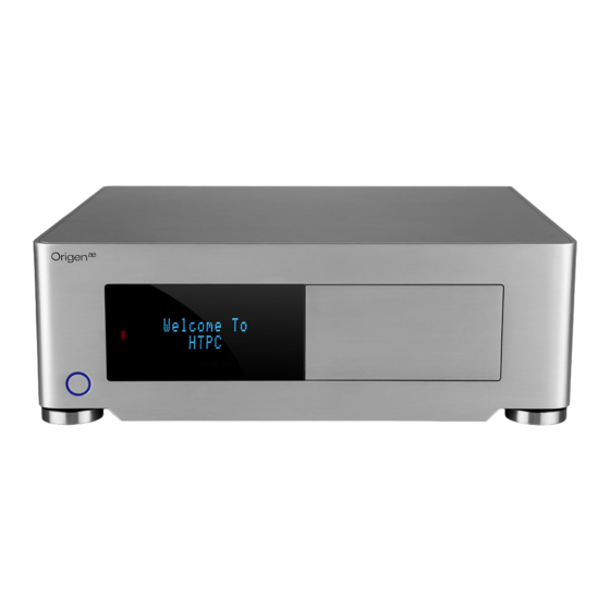
S10V overview These are the main features and controls of the S10V htpc enclosure. Power button Power LED ring One piece aluminum chassis VFD/IR acryl window Top panel Slot for optical disk drive (ODD) ODD eject button Soft-eject access panel... -
Page 5: S14V Overview
S14V overview These are the main features and controls of the S14V htpc enclosure. Power button Power LED ring One piece aluminum chassis VFD/IR acryl window Top panel Optical disk drive (ODD) bezel Soft-eject access panel I/O ports /multi-format card reader ODD eject button Door latch Intake vent... -
Page 6: S16V Overview
S16V overview These are the main features and controls of the S16V htpc enclosure. Power button Power LED ring One piece aluminum chassis VFD/IR acryl window Top panel Optical disk drive (ODD) bezel Soft-eject access panel I/O ports /multi-format card reader ODD eject button Door latch Fixing point for HM100 (see 23) -
Page 7: Opening The Case
Opening the case Remove the thumb screws as indicated. Carefully raise the p anel as shown (about 30mm is enough) pull out to remove. Reverse the procedure to replace. DO NOT force upwards as this could cause damage to the top panel. ODD cage removal [S14V/S16V] Hard drive cage... -
Page 8: Metal Sticker Fitting Instructions
Metal sticker fitting instructions [S14V/S16V] The drive format icon should also be fitted to the bezel before installation. The metal sticker sheet supplied has Blu-ray, HD-DVD or DVD icons, depending on the format being used. Ensure the bezel is free from dirt of grease. Peel and fold back the yellow backing sheet, revealing only the part you wish to use. -
Page 9: Optical Disk Drive Installation
ODD bracket Hard Drive installation [S10V] The S10V supports 2 hard drives. Each HD requires four anti-vibration screws, secured as shown, which will isolate the drive from the chassis once installed . A single mount bracket is push fitted over the mount screws on the one side only. The drive may then be positioned between the chassis mounts as shown, and gently pushed into place, taking care not to damage the rubber on the mount screws. -
Page 10: Hard Drive Installation
Hard Drive installation [S14V/S16V] mount The S14V and S16V support up to screw 4 hard drives*, three in the primary HD cage and one above the ODD. Each HD requires four anti-vibration mount screws, secured as shown, which will isolate the drive from the chassis once installed . -
Page 11: Auxiliary Access Slot
The S14V & S10V features an auxiliary access slot Both the S10V & S14V have an on the back of the chassis, which is designed to fit IR blaster fixing point on the rear of the chassis, for when the all expansion brackets that are supplied with other OrigenAE products. -
Page 12: Multi-Format Card Reader & I/O Ports
Multi-format card reader & I/O ports All the S range cases come fitted with a multi-format card reader and front I/O port PCB which consist of audio in and out, 1394 and two ports. A built- in USB hub powers the front USB ports as well as 2 internal connectors, which are used for the IR controller, VFD or [TFT] touch panel, depending on the model. -
Page 13: Pcb/Cable Reference Diagram
1 - VFD/IR Module (VF210) PCB/cable reference diagram 2 - [VFD] IR selector switch (IR Trans is default) This is a general overview illustrating 3 - [VFD] LED switch (IR Trans: 2=ON 1=OFF) how the internal PCBs interconnect. Grey 4 - Main power button PCB PCBs/cables indicate they come as part 5 - Standby power ‘Y’... -
Page 14: Installing Vfd/Ir Software
Installing VFD/IR Software Download the latest IR Trans software from our website, extract the files then follow these steps... Begin the Installer will installer by double unpack and verify clicking the IR its contents Trans setup file The main IR Trans installer page Please read installation notes then click next will load, click next to continue Ensure that you’ve selected the MCE Display... - Page 15 You can change the default menu group You are not ready to start the file installation, setting then click next to continue click next to begin Files and setting will now be copied and Installation is now complete applied, please wait for this to finish and a reboot is required...
- Page 16 Origen Global HQ #209 Baeksan B/D 763-2 Hengsin-Dong Dukyang-Gu Goyang City Gyounggi-Do 412-220 South Korea Website www.origen .com...
Need help?
Do you have a question about the S10V and is the answer not in the manual?
Questions and answers