Advertisement
Table of Contents
Advertisement
Table of Contents

Related Manuals for Origen ae M10


Summary of Contents for Origen ae M10
- Page 1 user guide Origen...
- Page 2 user guide Thank you for purchasing this Origen htpc enclosure. We recommend that you read this user guide thoroughly before installation. Origen has rapidly grown to be one of the worlds leading HTPC enclosure manufacturers since its inception in 2000. We were one of the first companies with the vision to produce high end htpc enclosures that harmonise with mainstream audio visual equipment, allowing the pc to leave the office and fit effortlessly into the living room environment.
-
Page 3: Table Of Contents
M10 overview / Accessories Opening the case Optical disk drive installation Hard drive installation Mainboard installation Max height CPU cooler VF310 cable reference diagram Installing VFD/IR Software Adapter connecting / Specification... -
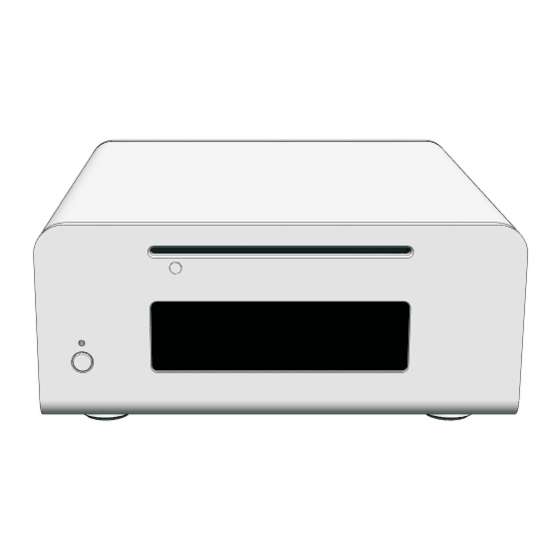
Page 4: M10 Overview / Accessories
M10 overview These are the main features and controls of the M10 htpc enclosure. Power button Power LED One piece aluminum chassis ODD eject button Slot for optical disk drive (ODD) VFD/IR acryl window Top panel Right mount panel(DC to DC, 60mm fan) -
Page 5: Opening The Case
Opening the case Remove the 4 fixing screws as indicated1. Carefully raise the panel as shown 2. Optical disc drive installation Loosen(no need to remove) the 4 fixing screws. Keyhole shaped holes allow the ODD bracket to slide up and be lifted out over the screw heads. -
Page 6: Hard Drive Installation
Hard Drive installation The M10 supports a 2.5 inch HDD or SSD. A HDD or SSD requires the 4 fixing screws on the left panel of the chassis as shown. Mounting holes Left side view Mainboard installation If a Mini-itx board is to be... -
Page 7: Vf310 Cable Reference Diagram
VF310 cable reference diagram 1 - VFD/IR module (VF310) This is a general overview illustrating how the 2 - IR selector switch ( S-GRAPH is default internal PCBs interconnect. The VFD should be 3 - Main power button PCB (M-PWBT-P1) switched to ‘S-GRAPH’... -
Page 8: Installing Vfd/Ir Software
Installing VFD/IR Software Read this notice before installation, The select switch must be a S-Graph in ● VF310 back sides S-Graph and Philips. The USB(M-IUSB-C1) cable must be ● connected to USB header pins. The 5V standby cable must be connected ●... -
Page 9: Adapter Connecting / Specification
Connecting adapter Connect external adapter(FSP150-AHAN1) to DC jack and AC cord to external adapter as shown. AC cord in Adapter specification (FSP150 - AHAN1) input rated input voltage - 100vac / 240 vac input voltage range - 90 vac to 264vac input frequency range - 47Hz to 63Hz - ≤2.0A... - Page 10 Origen Global HQ #209 Baeksan B/D 763-2 Hengsin-Dong Dukyang-Gu Goyang City Gyounggi-Do 412-220 South Korea Website www.origen .com...
Need help?
Do you have a question about the M10 and is the answer not in the manual?
Questions and answers