Table of Contents
Advertisement
Quick Links
Download this manual
See also:
Instruction Manual
QQ
3 7 63 1515 0
TE
L 13942296513
www
.
http://www.xiaoyu163.com
SERVICE MANUAL
SERVICE MANUAL
AV RECEIVER
DTR-8.4
MODEL
Standby/On
Standby
Direct/
Zone 2 (
)
GRN
Pure Audio
Rec (
RED
)
Audio
DVD
Video 1
Video 2
Selector
Pure Audio
U
psampling
VCR 1
VCR 2
BMDD
BMPA
SAFETY-RELATED COMPONENT
WARNING!!
COMPONENTS IDENTIFIED BY MARK
SCHEMATIC DIAGRAM AND IN THE PARTS LIST ARE
CRITICAL FOR RISK OF FIRE AND ELECTRIC SHOCK.
REPLACE THESE COMPONENTS WITH ONKYO
PARTS WHOSE PART NUMBERS APPEAR AS SHOWN
IN THIS MANUAL.
MAKE LEAKAGE-CURRENT OR RESISTANCE
MEASUREMENTS TO DETERMINE THAT EXPOSED
PARTS ARE ACCEPTABLY INSULATED FROM THE
SUPPLY CIRCUIT BEFORE RETURNING THE
APPLIANCE TO THE CUSTOMER.
x
ao
u163
y
i
http://www.xiaoyu163.com
2 9
8
Video 3
Video 4
Video 5
Tape
Tuner
Phono
CD
Net Audio
Black model
Q Q
3
6 7
1 3
120V, AC 60Hz
230~240V, AC 50Hz
ON THE
.
1
9 4
2 8
Ref. No. 3788
Dec., 2003
Master Volume
Display
Push To Open
DTR-8.4
1 5
0 5
8
2 9
9 4
m
co
DTR-8.4
9 9
2 8
9 9
Advertisement
Table of Contents

Related Manuals for Integra DTR-8.4


Summary of Contents for Integra DTR-8.4
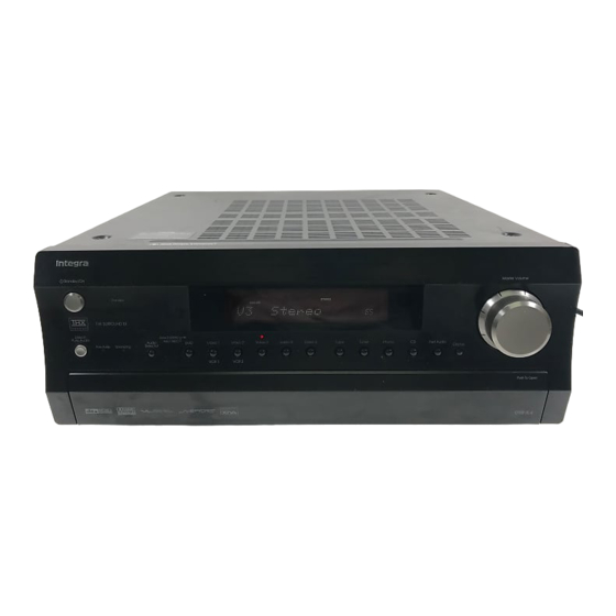
- Page 1 DTR-8.4 3 7 63 1515 0 Ref. No. 3788 SERVICE MANUAL SERVICE MANUAL Dec., 2003 AV RECEIVER DTR-8.4 MODEL Standby/On Master Volume Standby Direct/ Zone 2 ( Pure Audio Rec ( Audio Video 1 Video 2 Video 3 Video 4...
-
Page 2: Specifications
DTR-8.4 3 7 63 1515 0 SPECIFICATIONS Amplifier Section General Power output: 110 W (8 , 20 Hz~20 kHz, FTC) Power supply: American model: AC 120 V, 60 Hz All channels: (American Model) Australian model: AC 230~240 V, 50 Hz... -
Page 3: Service Procedures
DTR-8.4 3 7 63 1515 0 SERVICE PROCEDURES 1. Replacing the fuses 3. Safety-check out (U.S.A. model only) This symbol located near the fuses indicates After correcting the original service problem, perform the that the fuse used is fast operating type. For continued following safety check before releasing the set to the customer. - Page 4 20 21 25 26 27 28 Standby/On button Input selector buttons & indicators This button is used to set the DTR-8.4 to On or These buttons are used to select the following input Standby. sources: DVD, VIDEO 1~5, TAPE, TUNER, PHONO, CD, and NET AUDIO.
-
Page 5: Front Panel
Tuning [ ] buttons This control is used to set the volume of the These buttons are used to tune into radio stations DTR-8.4 from 0 to 100. and to select items on the onscreen setup menus (OSD). Direct/Pure Audio button... - Page 6 DTR-8.4 3 7 63 1515 0 PANEL VIEWS DISPLAY Audio input format indicators Multipurpose display area These indicators sho w the audio input format for the Normally, the name of the currently selected input currently selected input source. source is displayed here. When you select the AM or FM input source, the radio frequenc y and preset Listening mode &...
-
Page 7: Rear Panel
These analog inputs can be used to connect a CD L/R surround back inputs on a separate power amp player with analog outputs. when the DTR-8.4 is used as a preamp, or to feed a power amp in Zone 2. u163... - Page 8 MONITOR OUT If you want to use the remote controller to control the DTR-8.4 from Zone 2, or if the DTR-8.4 is This S-V ideo or composite video output can be con- installed in a cabinet and the line of sight between nected to the video input on your TV or projector .
-
Page 9: Amp Mode
The DTR-8.4' s remote controller is a multipurpose Surround button de vice that can be used to control not just the DTR-8.4 This button is used to select the Dolby and DTS lis- but your other AV components as well. This section tening modes. -
Page 10: Net-Tune Mode
] button is Muting button used to select the next track. This button is used to mute the DTR-8.4. This func- Pause [ ] button tion can be set only with the remote controller. This button is used to pause playback. -
Page 11: Dvd Mode
During playback it selects trol it with the DTR-8.4' s remote controller. You only the beginning of the current chapter or track. The need to point the remote controller at the DTR-8.4. - Page 12 Setup/Guide button This button is used to access the DVD player' s onscreen setup menus. Muting button This button is used to mute the DTR-8.4. This func- tion can be set only with the remote controller . Play [ ] button This button is used to start DVD playback.
- Page 13 VOL button This button is used to set the volume of the DTR-8.4. Muting button This button is used to mute the DTR-8.4. This func- tion can be set only with the remote controller. Play [ ] button This button is used to start CD playback.
-
Page 14: Minidisc Mode
DTR-8.4. MiniDisc Mode Muting button This button is used to mute the DTR-8.4. This func- MiniDisc mode is used to control an Integra/Onkyo tion can be set only with the remote controller . MiniDisc recorder connected to the DTR-8.4 via . To... -
Page 15: Tape Mode
VOL button This button is used to set the volume of the DTR-8.4. Muting button This button is used to mute the DTR-8.4. This func- tion can be set only with the remote controller. Play [ ] button This button is used to start tape playback. -
Page 16: Exploded View
DTR-8.4 3 7 6 3 1 5 1 5 0 EXPLODED VIEW P1010 P603 P603C P602 P7201 P7701 F901 L 1 3 9 4 2 2 9 6 5 1 3 P2901 F902 Q6062 F903 Q6052 Q6056 Q9422B F9501A... -
Page 17: Block Diagram
DTR-8.4 3 7 63 1515 0 BLOCK DIAGRAM DIGITAL AUDI O INPUT OPTI CAL VIDEO 5 DIGITAL AUDI O OUTPU T 24.576MHZ (FRONT) OPTI CAL 1 SRAM COAX IAL 1 CY7C CY7C 1019BV33 1019BV33 TC92 COAX IAL 2 OPTICAL 2 24.576MHZ... - Page 18 DTR-8.4 3 7 63 1515 0 BLOCK DIAGRAM 11dB MUTE MULTICHANNEL INPUT 11dB HEAD PHONE MUTE HPEN MASTER VOLUM E TONE PREOUT NJU7 306G LEFT Power Amplif ier BOOST MUTE +29d B SL->L C->L SW->L BYPASS TC94A07F FRON T SPEAKE RS...
-
Page 19: Schematic Diagram
DTR-8.4 3 7 63 1515 0 SCHEMATIC DIAGRAM 1 DISPLAY AND SUB MICROPROCESSOR SECTIONS P7201A TO NAAR-8078 (SCH. 9) TO NAPS-7708 (SCH. 7) JL720 NAETC-7742 L2576 NCH-1471 U2501 DGND TORX178A R2576 C7501 474Z NAETC-7741 R7501 P2508 R7502 NAETC-7740 C7502... - Page 20 DTR-8.4 3 7 63 1515 0 SCHEMATIC DIAGRAM 1 DISPLAY AND SUB MICROPROCESSOR SECTIONS . 7) JL7201A Q7501 16-BT-115GNK or HNA-16M M40T Q7504 Q7503 2SC2712 7502 220 KTC3875 7502 474Z 7509 474Z 7501 UDZ11B 7510 C7520 104Z Q7502 M66005FP...
- Page 21 DTR-8.4 3 7 63 1515 0 SCHEMATIC DIAGRAM 2 DSP and Main microprocessor sections NADG-7687 P701 DSP1GP8" R7102 DSP1GP9" DSP1GP10" R7103 C706 104Z VSS1 1 VDDI 3 60 Q706 R730 1K INT1" Q705 CY7C 1019BV33 -15VCT CY7C 1019BV33 -15VCT...
- Page 22 DTR-8.4 3 7 63 1515 0 DSPDA (SCH.7) DSPC L TO MAIN AMP NADG-7687 P7701A SCHEMATIC DIAGRAM 2 DSP and Main microprocessor sections KRC1 04S Q7001 RN14 04 C7004 1/50 CSTC V16.0MXJ UDZ6 .2B D700 5 D7004 +13V FLAS HDO...
- Page 23 DTR-8.4 3 7 63 1515 0 SCHEMATIC DIAGRAM 3 Audio I/O terminal section NAAF-7720 NJM4565M-D Q3205 C3222 47/50 R3222 R3234 R3252 220K AGND 100K R3223 R3235 220K R3250 100K C3223 Q3205 47/50 R3251 C3252 R3253 100K 10/16 R3254 100K...
- Page 24 DTR-8.4 3 7 63 1515 0 SCHEMATIC DIAGRAM 3 Audio I/O terminal section TO TUNER PACK P1010A NAAF-7719 C1006 3.3/50 Q1001 78M12 R1005 R1000 R1001 100K R1004 C1002 C1001 100K 10/16 104Z R1003 100K C1005 R1006 C1007 R1002 101J...
- Page 25 DTR-8.4 3 7 63 1515 0 SCHEMATIC DIAGRAM 4 Preamplifier section P3600 R3600 C3610 10/50 LEFT R4120 C4120 C3600 R3610 R3620 22 (1/2W) C4200 220/16 R4320 331K 220K Left 10/50 FRONT C4320 R3611 R3621 C3601 (1/2W) C4121 R4121 220/16...
- Page 26 DTR-8.4 3 7 63 1515 0 SCHEMATIC DIAGRAM 4 Pre amplifier section NAAF-7718 R4920 22 (1/2W) C4920 C4802 C4230 R4410 C4800 220/16 NJM4565M-D 2.2/50 47/50 4.7K 10/16 C4806 C4220 C4210 R4420 R4814 Q4210 Q4410 100/6.3 1/50 100D 4.7K R4800...
- Page 27 DTR-8.4 3 7 63 1515 0 SCHEMATIC DIAGRAM 5 Driver section NAAF-7707 R5303 R5143 R5133 R5183 R5233 100(1/4W) R5113 R5123 (1/4W) (1/4W) (1/4W) (1/4W) 56.5V 2.2K 2.2K R5073 56.6V 100K 55.9V Q5053 Q5043 56.1V 1.2V 56.0V Q5033 C5123 C5113...
- Page 28 DTR-8.4 3 7 63 1515 0 SCHEMATIC DIAGRAM 5 Driver section NAAF-7690 R5300 57.5V R5140 R5130 R5180 R5230 68 (1/4W) R5110 R5120 (1/4W) (1/4W) (1/4W) 56.6V (1/4W) 2.2K 2.2K R5070 51.5V 100K 56.3V Q5050 55.8V Q5040 1.2V Q5030 C5120...
- Page 29 DTR-8.4 3 7 63 1515 0 SCHEMATIC DIAGRAM 6 Power amplifier section NAAF-7706 58.3V Q6033 Q6003 1.2V R6083 R6163 Q6053 R6013 C6512 0.6V (1/4W) 5.6K 4.7/100 Q6073 0.5V R6143 P6083 R6023 0.1V R6063 3.9K R6512 3.3K R6103 0.22 R6033 0.22...
- Page 30 DTR-8.4 3 7 63 1515 0 SCHEMATIC DIAGRAM 6 Power amplifier section R6230 58.2V R6270 58.3V R6080 Q6000 1.2V (1/4W) (1/4W) (1/2W) R6160 Q6050 R6010 Q6030 Q6090 R6510 4.7K 57.7V 0.22 Q6070 R6140 0.5V (1/2W) R6250 L6000 0.6V R6020...
- Page 31 DTR-8.4 3 7 63 1515 0 SCHEMATIC DIAGRAM 7 Power supply and speaker terminal sections P TYPE P TYPE NAETC-7695 NAETC-7694 P6800 L6800 S1.3C L6803 S1.3C SPEAKERS R6800 22 R6803 22 R6810 22 R6813 22 D TYPE D TYPE...
- Page 32 DTR-8.4 3 7 63 1515 0 SCHEMATIC DIAGRAM 7 Power supply and speaker terminal sections NAPS-7691 C922 220/35 C921 R926 P6802 4.7K SPEAKERS 223Z R924 (1/2W) +13V MPUGND R922 POWER 4.7K E921 Q921 T901 D921-D924 R923 D925 GP104003E OR 2SC1740S 4.7K...
- Page 33 DTR-8.4 3 7 63 1515 0 SCHEMATIC DIAGRAM 8 Net-tune circuit section NADG-7662 3.3V 2.5V Voltage Regurator +2.5V MultiMedia CPU +5.6V +2.5V +3.3V +3.3V +5.6V L603 Q601 BA33C25FP +3.3V NFM60R10T471 BLM21P221SG VO1 4 L601 Main Me VO2 5 Q607 Q603 +3.3V...
- Page 34 DTR-8.4 3 7 63 1515 0 SCHEMATIC DIAGRAM 8 Net-tune circuit section +3.3V (NETWORK SECTION) 10BaseT EtherNet +3.3V Main Memory Program Flash ROM R601 100_1% P601 R553 100_1% Q603 R555 27K_5% +3.3V DQ15 53 SA19 RXD+ DQ14 51 R602 100_1%...
- Page 35 DTR-8.4 3 7 63 1515 0 SCHEMATIC DIAGRAM 9 Main and control terminal sections (SCH.1) P7201B NAETC-8083 NAAR-8078 P201 C4+ 20 RS-232 L201 GND19 BLM21A102F C4- 18 C204 VSS 17 1/50 C202 STBY16 1/50 VCHA15 SUBREQ R205 R201 330...
- Page 36 DTR-8.4 3 7 63 1515 0 SCHEMATIC DIAGRAM 9 Main and control terminal sections (SCH.7) P9502B R2912 1/2W R2931 D2931 RL1N4003 1 1/2W R2933 D2902 RL1N4003 22 (1/2W) 1SS352 R2902 D2932 Q2907 Q2903 D2903 2SC2712 2SC2712 Q2902 Q2908 R2903...
- Page 37 DTR-8.4 3 7 63 1515 0 SCHEMATIC DIAGRAM 10 Component and S video sections TO NAAR-8078 (SCH.9) P2705B P2855B D2804 1SS352 RL2804 Q2751 TC90A69F C2751 C2764 103Z BIAS 103Z C2752 103Z COUT D2803 C2753 100/6.3 1SS352 220K C2803 VDD1...
- Page 38 DTR-8.4 3 7 63 1515 0 SCHEMATIC DIAGRAM 10 Component and S video sections NAVD-8069 R2403 75 P2501 R2401 75 MONITOR C2764 Q2403 103Z C2433 Q2721 104Z C2432 C2723 DVDC R2723 L2721 DVDY 2SC2712 100/6.3 104Z 220K P2502 DVDY...
- Page 39 DTR-8.4 3 7 63 1515 0 SCHEMATIC DIAGRAM 11 Composite video section NAVD-8079 Q2001 LC74761M-9848 X2001 Vdd1 XTL14.32MH Z Q2301 C2001 100D XTALIN1 SYNCDET C2002 180J XTALOUT1 R2302 P2001 Q2302 VCOOUT MONITOR R2301 HSYNCOUT C2003 X2002 Except VCOIN 330J 17.73MHZ...
- Page 40 DTR-8.4 3 7 63 1515 0 SCHEMATIC DIAGRAM 11 Composite video section Q2001 LC74761M-9848 C2010 100/6.3 X2001 Vdd1 R2009 C2011 474J XTL14.32MH Z 47K R2010 C2001 100D XTALIN1 C2012 0.47/50 D2001 2.7K SYNCDET C2002 180J XTALOUT1 C2013 270J VCOOUT...
-
Page 41: Wiring View
DTR-8.4 3 7 63 1515 0 WIRING VIEW 1 CONTROL TERMINAL PC BOARD (NAETC-8083) P204 P203 P202 P201 P205 P606B P607B MAIN CONNECTOR (SCH. 9) PC BOARD P602B (NAAR-8078) P605 (SCH. 9) NET-TUNE PC BOARD P603A (NADG-7662) (SCH. 8) - Page 42 DTR-8.4 3 7 63 1515 0 WIRING VIEW 1 P3601 P3600 P4601 P4600 U105 U104 U103 U102 U101 U100 P101 PREAMPLIFIER PC BOARD (NAAF-7718) P800 (SCH. 4) FRONT OPTICAL INPUT PC DSP CIRCUIT BOARD PC BOARD (NAETC-7722) (NADG-7687) P750 (SCH.
- Page 43 DTR-8.4 3 7 63 1515 0 WIRING VIEW 2 NAETC-8086 THERMAL DET. NAETC-8085 PC BOARD THERMAL DET. (SCH.7) PC BOARD 120V model only (SCH.7) 120V model only POWER SUPPLY JL9504B PC BOARD (NAPS-7708) (SCH. 7) P9502A P9508 JL9503B FAN DRIVE...
- Page 44 DTR-8.4 3 7 63 1515 0 WIRING VIEW 2 P5004E P5003E PREAMPLIFIER PC BOARD (NAAF-7718) (SCH. 4) BIAS SELECTOR JL4612 RELAY PC BOARD P4012A (NAPS-7692) (SCH. 7) P4020B P4010B P4011B JL6953B P6951 P901B AC INLET TERMINAL P9505A PC BOARD (NAETC-7700) (SCH.
- Page 45 DTR-8.4 3 7 63 1515 0 PRINTED CIRCUIT BOARD VIEW FROM SOLDERING SIDE 1-1 S7569 C7559 C7569 S7569 COMPONENT SIDE SOLDERING SIDE VOLUME PC BOARD(NAETC-7739) C7481 C7482 J772 J771 P7482B C7483 25137740 NCETC-7740 L 13942296513 COMPONENT SIDE SOLDERING SIDE...
- Page 46 DTR-8.4 3 7 63 1515 0 PRINTED CIRCUIT BOARD VIEW FROM SOLDERING SIDE 1-2 P7203 J7273 J7266 J7282 Q7501 VDCS C7207 SUBPOFF MAINREQ SYNC FLOSDDA FLOSDCL Q7501 OSDCS DIMPWM REMIN J7272 VDDA SUBRES VDCL VSYNC 232RX U7201 232TX NETRX...
-
Page 47: Display Circuit
DTR-8.4 3 7 63 1515 0 PRINTED CIRCUIT BOARD VIEW FROM SOLDERING SIDE 1-3 JL7201A J7242 D7533 J7243 POWER S7541 STANDBY NCDIS-7738 25137738A COMPONENT SIDE J7213 J7224 D7523 D7522 D7524 J7229 D7521 J7219 J7230 VIDEO1 AUDIOSEL VIDEO3 VIDEO2 J7228... - Page 48 DTR-8.4 3 7 63 1515 0 PRINTED CIRCUIT BOARD VIEW FROM SOLDERING SIDE 2-1 C720 C719 25137687B R133 P603B C712 R740 R155 Q130 R154 P701 R153 R152 R151 P701 9 9 9 R149 Q130 C155 C154 C153 C 53...
- Page 49 DTR-8.4 3 7 63 1515 0 PRINTED CIRCUIT BOARD VIEW FROM SOLDERING SIDE 2-2 C720 C720 C720 C720 C720 25137687B 25137687B 25137687B 2 13 68 B 25137687B L 13942296513 u163 SOLDERING VIEW FOR CHIP PARTS DSP CIRCUIT PC BOARD (NADG-7687) http://www.xiaoyu163.com...
- Page 50 DTR-8.4 3 7 63 1515 0 PRINTED CIRCUIT BOARD VIEW FROM SOLDERING SIDE 2-1 C763 Q705 R789 Q707 L 13942296513 2 2 2 R7173 C7008 Q7102 Q7102 R7184 R7185 R7047 R7047 R7045 R7044 R7043 R7042 R704 Q700 000 0 0...
- Page 51 DTR-8.4 3 7 63 1515 0 PRINTED CIRCUIT BOARD VIEW FROM SOLDERING SIDE 2-2 L 13942296513 u163 SOLDERING VIEW FOR CHIP PARTS DSP CIRCUIT PC BOARD (NADG-7687) http://www.xiaoyu163.com...
-
Page 52: Printed Circuit Board View
DTR-8.4 3 7 63 1515 0 PRINTED CIRCUIT BOARD VIEW 3-1 COMPONENT SIDE L 13942296513 R1 1 006 u163 SOLDERING SIDE AUDIO TERMINAL PC BOARD (NAAF-7719) http://www.xiaoyu163.com... - Page 53 DTR-8.4 3 7 63 1515 0 PRINTED CIRCUIT BOARD VIEW 3-2 P3201 P320 P3201 1 P3202 2 2 P3202 P3202 P3210A COMPONENT SIDE L 13942296513 SOLDERING SIDE u163 VIDEO TERMINAL PC BOARD (NAAF-7720) http://www.xiaoyu163.com...
- Page 54 DTR-8.4 3 7 63 1515 0 PRINTED CIRCUIT BOARD VIEW 4-1 COMPONENT SIDE L 13942296513 u163 PRE AMPLIFER PC BOARD SOLDERING SIDE (NAAF-7718) http://www.xiaoyu163.com...
- Page 55 DTR-8.4 3 7 63 1515 0 PRINTED CIRCUIT P461 P461 P461 P461 P461 BOARD VIEW 4-2 COMPONENT SIDE L 13942296513 SOLDERING SIDE u163 AMPLIFER PC BOARD (NAAF-7718) http://www.xiaoyu163.com...
- Page 56 DTR-8.4 3 7 63 1515 0 PRINTED CIRCUIT BOARD VIEW 5-1 J6005 J6005 J6010 J6011 J6011 L 13942296513 J6016 J6022 SURROUND DRIVER CIRCUIT PC BOARD u163 (NAAF-7690) http://www.xiaoyu163.com...
- Page 57 DTR-8.4 3 7 63 1515 0 PRINTED CIRCUIT BOARD VIEW 5-2 P6002A P6002A L 13942296513 P6001A C5001 C5001 K-P3X K P3X FRONT/CENTER DRIVER CIRCUIT PC BOARD (NAAF-7690) u163 http://www.xiaoyu163.com...
- Page 58 DTR-8.4 3 7 63 1515 0 PRINTED CIRCUIT BOARD VIEW 6-1 J6212 2 J6183 3 Q606 62 2 Q606 61 1 Q606 60 0 17 7 60 0 92 J J 6233 R652 AGND VOLH DCDET T DCDET P P RO...
- Page 59 DTR-8.4 3 7 63 1515 0 PRINTED CIRCUIT BOARD VIEW 6-2 J6183 3 Q6 6 051 Q6 6 050 P6201 J6184 P6204A + + B1 C6534 C6902 R6 6 0 J6126 6 J6110 C6901 C C 6902 P6211 P6211...
- Page 60 DTR-8.4 3 7 63 1515 0 PRINTED CIRCUIT BOARD VIEW FROM COMPONENT SIDE 8 L 13942296513 Component side u163 NET-TUNE CIRCUIT PC BOARD(NADG-7662) http://www.xiaoyu163.com...
- Page 61 DTR-8.4 3 7 63 1515 0 L 13942296513 Soldering side u163 NET-TUNE CIRCUIT PC BOARD(NADG-7662) http://www.xiaoyu163.com...
- Page 62 DTR-8.4 3 7 63 1515 0 PRINTED CIRCUIT BOARD VIEW 7-1 P6007A +24V +24V +24V FCSLRL FCSLRL FRONT/CENTER SPEAKER TERMINAL PC BOARD P6800 (NAETC-7694) P6800 0 L 13942296513 P6008A FCSLRL +24V +24V SBRL SBRL SURROUND SPEAKER TERMINAL 2 2 12...
- Page 63 DTR-8.4 3 7 63 1515 0 PRINTED CIRCUIT BOARD VIEW 7-2 6907 RL6901 RL6901 C950 C950 0 9 R944 4 4 1 C9441 R9 9 44 42 2 R944 R R 944 4 3 R944 BIAS SELECTOR CIRCUIT PC BOARD...
- Page 64 DTR-8.4 3 7 63 1515 0 PRINTED CIRCUIT BOARD VIEW 7-2 6907 RL6901 RL6901 C950 C950 0 9 R944 4 4 1 C9441 R9 9 44 42 2 R944 R R 944 4 3 R944 BIAS SELECTOR CIRCUIT PC BOARD...
- Page 65 DTR-8.4 3 7 63 1515 0 PRINTED CIRCUIT BOARD VIEW 7-3 DCDET DCD D ET CDE E T FANDET NDE E T DET T VOLH AGND D FAN DRIVE CIRCUIT PC BOARD (NAETC-7696) ETC-7698 CMK-P3X THERMAL DET. THERMAL DET.
- Page 66 DTR-8.4 3 7 63 1515 0 PRINTED CIRCUIT BOARD VIEW 9-1 P4011A MAIN CONNECTOR PC BOARD (NAAR-8078) L 13942296513 u163 http://www.xiaoyu163.com...
- Page 67 DTR-8.4 3 7 63 1515 0 PRINTED CIRCUIT BOARD VIEW 9-2 NCAR-8078 NCAR 8078 NCAR 8078 NCAR-8078 0 0 0 0 25138078A 25138078A 002A 002A R291 R291 SIDE P4011A MAIN CONNECTOR PC BOARD (NAAR-8078) NCETC-8 L 13942296513 CONTROL TERMINAL PC BOARD...
- Page 68 DTR-8.4 3 7 63 1515 0 PRINTED CIRCUIT BOARD VIEW 9-1 P800A MAIN CONNECTOR PC BOARD (NAAR-8078) L 13942296513 u163 http://www.xiaoyu163.com...
- Page 69 DTR-8.4 3 7 63 1515 0 PRINTED CIRCUIT BOARD VIEW 9-2 NCAR-8078 25138078A P4012A MAIN CONNECTOR PC BOARD (NAAR-8078) CETC 8 L 13942296513 P205 E201 P201 CONTROL TERMINAL PC BOARD (NAETC-8083) u163 http://www.xiaoyu163.com...
- Page 70 DTR-8.4 3 7 63 1515 0 PRINTED CIRCUIT BOARD VIEW 11 NCVD-807 25138079 Soldering side A (Parts location side) L 13942296513 NCVD-807 009 9 25138079 Soldering side B u163 COMPOSITE VIDEO PC BOARD (NAVD-8079) http://www.xiaoyu163.com...
- Page 71 DTR-8.4 3 7 63 1515 0 PRINTED CIRCUIT BOARD VIEW 10-2 P28 8 02 Soldering side A (Parts location side) L 13942296513 P280 0 2 P280 0 2 R R 2849 R2832 R2812 C2812 C 812 R R 2833...
- Page 72 DTR-8.4 3 7 63 1515 0 PRINTED CIRCUIT BOARD VIEW 10-1 Soldering side A (Parts location side) L 13942296513 3 3 3 u163 Soldering side B S VIDEO PC BOARD (NAVD-8069) http://www.xiaoyu163.com...
- Page 73 DTR-8.4 3 7 63 1515 0 MAIN MICROPROCESSOR-CONNECTION DIAGRAM Q6704 Q6070~Q6076 Q6703 GATE CURRENT GATE CIRCUIT DET. CIRCUIT Q604,Q607, Q4401 Q4400 THERMA Q616 TONE TONE DET. NETTUNE CONTROL CONTROL CIRCUIT NJU7308G NJU7308G RESET PIN POWER FAILURE DET. Q2821 VIDEO...
- Page 74 DTR-8.4 3 7 63 1515 0 MAIN MICROPROCESSOR-CONNECTION DIAGRAM Q6701,Q6702 VOLTAGE DETECTOR Shows a left channel only. Shows a left channel only. LEFT CH. SURROUND CENTER/SUB LEFT CH. WOOFER PRE RL6902 Q4600 Q4610 OUTPUT Q4603 Q4613 Q4602 Q4612 OUTPUT...
- Page 75 DTR-8.4 3 7 63 1515 0 SUB MICROPROCESSOR-CONNECTION DIAGRAM P204 F1 1 Q 7 2 0 2 B U F F E R P 7 4 8 1 P H O N E S S Y N C Y SIGNAL...
- Page 76 DTR-8.4 3 7 63 1515 0 SUB MICROPROCESSOR-CONNECTION DIAGRAM D 7 5 3 4 R E D Q 7 5 3 4 G R E E N D 7 5 3 2 D 7 5 3 0 D 7 5 3 1...
- Page 77 DTR-8.4 3 7 6 3 1 5 1 5 0 MAIN MICROPROCESSOR-TERMINAL DESCRIPTION Function Description Function Description 1 DSPDA Serial data output pin to transfer the data to DSP, DIR, Nettune DAC and Second PLL ICs. 51 ~CODECPD Power down output pin of CODEC IC.
-
Page 78: Adjustment And Confirmation Procedures
DTR-8.4 3 7 63 1515 0 ADJUSTMENT AND CONFIRMATION PROCEDURES 1 Idling current adjustment Before Idling current adjustment, turn the trimming resistors R6040 to R6046 to counter-clockwise. Connect the DC voltmeter at the sockets P6080 to P6086. After turn POWER to ON, adjust the trimming resistors R6040, R6041 and R6042 so that the reading of voltmeter becomes 11 mV. - Page 79 DTR-8.4 3 7 63 1515 0 ADJUSTMENT AND CONFIRMATION PROCEDURES 2 3. Confirmation of Current detection circuit Set the unit to "TEST-1-00". Connect the differentiating circuit and apply the 200Hz square signal to MULTI CHANNEL INPUT terminal of each channel.
-
Page 80: Test Mode
DTR-8.4 3 7 63 1515 0 ADJUSTMENT AND CONFIRMATION PROCEDURES 3 Test Mode 1. Turn POWER button on. 2. Press and hold down CD button, then press DISPLAY and STANDBY/ON buttons. 3. After "TEST " on the FL tube is displayed, press CD button to set the unit to the test mode of FL tube. -
Page 81: Packing View
DTR-8.4 3 7 63 1515 0 PACKING VIEW Accessory bag 7*100 Tape Speaker Cab le Bottom side P901 Knob side L 13942296513 Insert a protection sheet between a door and a front panel, and close a door. u163 http://www.xiaoyu163.com... -
Page 82: Exploded View Parts List
http://www.xiaoyu163.com EXPLODED VIEW-PARTS LIST 3 7 63 1515 0 NOTE: THE COMPONENTS IDENTIFIED BY MARK ! ARE CRITICAL FOR RISK OF FIRE AND ELECTRIC SHOCK. REPLACE ONLY WITH PART NUMBER SPECIFIED. CAUTION: Replacement for transistor of mark *, if necessary must be made from the same beta group (h ) as the original type. - Page 83 http://www.xiaoyu163.com REF. NO. PART NO. DESCRIPTION 3 7 63 1515 0 801606 3SMH10W.SW+15B(CU),Special screw 801608 TRX M4x8, Truss screw 838440089 4TTB+8C(BC),Self-tapping screw 801612 3TTB+8B(CU),Self-tapping screw 830440089 4TTC+8C(BC),Self-tapping screw 831430088 3TTW+8B(BC),Self-tapping screw 838120088 2TTB+8B,Self-tapping screw 838430088 3TTB+8B(BC),Self-tapping screw 838430107 3TTB+10S(BC),Self-tapping screw 838450108 5TTB+10B(BC),Self-tapping screw 838930088...
- Page 84 http://www.xiaoyu163.com REF. NO. PART NO. DESCRIPTION 3 7 63 1515 0 1A996538-2E NADIS-7738-2E,Display circuit PC board ass'y <D> 1A996538-2F NADIS-7738-2F,Display circuit PC board ass'y <A> 1A996539-2E NAETC-7739-2E,Master volume PC board ass'y <D> 1A996539-2F NAETC-7739-2F,Master volume PC board ass'y <A> 1A996540-2E NAETC-7740-2E,Headphone terminal PC board ass'y <D>...
-
Page 85: Packing Parts List
http://www.xiaoyu163.com PACKING-PARTS LIST 3 7 63 1515 0 REF. NO. PART NO. DESCRIPTION 29054094 Carton box 29363508 Label UPC 29100153 1020x770,Poly bag 29092125B 29100217 t0.1*70*100,Poly bag 29100097-1A 350*250,Poly bag 29110148 Tape PP 29095906 Protection sheet 29110149 Tape, cellophane 29363059A Label, speaker cable 29355450 Instruction sheet, caution 29343578... - Page 86 http://www.xiaoyu163.com 3 7 6 3 1 5 1 5 0 PRINTED CIRCUIT BOARD-PARTS LIST NOTE: THE COMPONENTS IDENTIFIED BY MARK ! ARE CRITICAL FOR RISK OF FIRE AND ELECTRIC SHOCK. REPLACE ONLY WITH PART NUMBER SPECIFIED. CAUTION: Replacement for transistor of mark *, if necessary must be made from the same beta group (h ) as the original type.
- Page 87 http://www.xiaoyu163.com 3 7 6 3 1 5 1 5 0 Oscillator X7201 3010322 CST16.00MXW0C1 Capacitors C2577,C2578 332161040R1 CK725F1E-104Z1, Ceramic C7201,C7202 355721019 CE04W6.3V-100M,Elect. C7203 375524744 MMT50V-474J,Plastic film C7204,C7206 332174740R1 CK725F1C-474Z1,Ceramic C7207 355721019 CE04W6.3V-100M,Elect. C7208 332161040R1 CK725F1E-104Z1, Ceramic C7213,C7214 332101025R1 CK725B1H-102K1,Ceramic C7293~C7295 332101025R1 CK725B1H-102K1,Ceramic C7297...
- Page 88 http://www.xiaoyu163.com 3 7 6 3 1 5 1 5 0 R7289 435030004R1 RN72K1J-000JE,Carbon <D> R7289 435031034R1 RN72K1J-103JE,Carbon <A> R7290 435033334R1 RN72K1J-333JE,Carbon <A> R7293~R7295 435034724R1 RN72K1J-472JE,Carbon R7297,R7330 435034724R1 RN72K1J-472JE,Carbon R7300,R7309 435031034R1 RN72K1J-103JE,Carbon R7301 435032244R1 RN72K1J-224JE,Carbon R7315,R7316 435031024R1 RN72K1J-102JE,Carbon R7329 435031034R1 RN72K1J-103JE,Carbon R7338~R7340 435031034R1 RN72K1J-103JE,Carbon...
- Page 89 http://www.xiaoyu163.com 3 7 6 3 1 5 1 5 0 R7567,R7577 435033924R1 RN72K1J-392JE,Carbon CIRCUIT NO. PART NO. DESCRIPTION Resistors R7571 435034714R1 RN72K1J-471JE,Carbon R7578 435031234R1 RN72K1J-123JE,Carbon R7601~R7604 435030004R1 RN72K1J-000JE,Carbon Switches S7541~S7549 25035714 or NPS-111-S677 or S7551~S7559 25035718 NPS-111-S681 S7561~S7568 25035714 or NPS-111-S677 or S7571~S7579 25035718...
- Page 90 http://www.xiaoyu163.com 3 7 6 3 1 5 1 5 0 R2571,R2572 435033314R1 RN72K1J-331JE,Carbon R2573~R2575 435037504R1 RN72K1J-750JE,Carbon Terminal P2510 25045678 NPJ-3PDB475 Sockets P2506B 2009990575UL NSAS-10P0784 P2508 25051569 NSCT-4P1356 P3220B 2009990420 NSAS-6P0564 OPTICAL INPUT PC BOARD (NAETC-7742-2E/2F) CIRCUIT NO. PART NO. DESCRIPTION Photo coupler U2501 24120101...
- Page 91 http://www.xiaoyu163.com 3 7 6 3 1 5 1 5 0 Q703 22241847R3 MB86344BPFV Q705,Q706 22241612R2 or CY7C1019BV33-15VCT or 22241887R2 CY7C1019CV33-15VCT Q7100,Q7101 22274541ER2TO or TC74VHC541FT or 22274541IR2TI SN74AHC541PWR Q7102 222740077R2TO TC74HCT7007AF Q800 22241521R3 AK4356VQ Q801~Q804 22241449R2, NJM5532M-D, 22241409R2 or BA15532F or 22241472R2 NJM2114M-D Photo couplers...
- Page 92 http://www.xiaoyu163.com 3 7 6 3 1 5 1 5 0 CIRCUIT NO. PART NO. DESCRIPTION Capacitors C100,C101 356744709R2 CEWX16V-47M,Elect. C102,C103 356724709R2 CEWX6.3V-47M,Elect. C104~C107 342101014R1 CC725CH1H-101J1,Ceramic C108,C110 356724709R2 CEWX6.3V-47M,Elect. C111,C115 332161040R1 CK725F1E-104Z1, Ceramic C113,C114 373021524R2 ECHU50V-152J,Chip film C116,C119 356723319R2 CEWX6.3V-330M,Elect. C118 342101014R1 CC725CH1H-101J1,Ceramic C120~C122...
- Page 93 http://www.xiaoyu163.com 3 7 6 3 1 5 1 5 0 C7005 356721019R2 CEWX6.3V-100M,Elect. C7006~C7010 332161040R1 CK725F1E-104Z1, Ceramic C702,C703 342102204R1 CC725CH1H-220J1,Ceramic C704~C712 332161040R1 CK725F1E-104Z1, Ceramic C7100,C7101 332161040R1 CK725F1E-104Z1, Ceramic C719,C720 3567A1019R2 CEWX4V-100M,Elect. C751~C763 332161040R1 CK725F1E-104Z1, Ceramic C764~C766 3567A1019R2 CEWX4V-100M,Elect. C767,C768 332161040R1 CK725F1E-104Z1, Ceramic C769,C770 342102204R1...
- Page 94 http://www.xiaoyu163.com 3 7 6 3 1 5 1 5 0 R150 435032214R1 RN72K1J-221JE,Carbon R151~R153 435031024R1 RN72K1J-102JE,Carbon R154,R155 435032214R1 RN72K1J-221JE,Carbon R156 435031834R1 RN72K1J-183JE,Carbon R157~R160 435034714R1 RN72K1J-471JE,Carbon R161,R162 435031524R1 RN72K1J-152JE,Carbon R163 435035624R1 RN72K1J-562JE,Carbon R164 435031014R1 RN72K1J-101JE,Carbon R165,R173 435031034R1 RN72K1J-103JE,Carbon R166~R168 435031024R1 RN72K1J-102JE,Carbon R169,R193 435034704R1 RN72K1J-470JE,Carbon...
- Page 95 http://www.xiaoyu163.com 3 7 6 3 1 5 1 5 0 R7087~R7092 435033314R1 RN72K1J-331JE,Carbon R709~R712 435034704R1 RN72K1J-470JE,Carbon R7093~R7097 435031024R1 RN72K1J-102JE,Carbon CIRCUIT NO. PART NO. DESCRIPTION Resistors R7102,R7109 435031034R1 RN72K1J-103JE,Carbon R7103 435031004R1 RN72K1J-100JE,Carbon R7104~R7107 435031024R1 RN72K1J-102JE,Carbon R7110 435032234R1 RN72K1J-223JE,Carbon R7112 435034734R1 RN72K1J-473JE,Carbon R7119 435031054R1 RN72K1J-105JE,Carbon...
- Page 96 http://www.xiaoyu163.com 3 7 6 3 1 5 1 5 0 R811~R814 435033324R1 RN72K1J-332JE,Carbon R815~R818 435030004R1 RN72K1J-000JE,Carbon R819~R822 435033324R1 RN72K1J-332JE,Carbon R823,R824 435030004R1 RN72K1J-000JE,Carbon R825,R826 435033324R1 RN72K1J-332JE,Carbon R827~R830 435031224R1 RN72K1J-122JE,Carbon R831~R834 435032224R1 RN72K1J-222JE,Carbon R835~R838 435031224R1 RN72K1J-122JE,Carbon R839,R840 435032224R1 RN72K1J-222JE,Carbon R841,R842 435031224R1 RN72K1J-122JE,Carbon R843~R858 435034724R1 RN72K1J-472JE,Carbon...
- Page 97 http://www.xiaoyu163.com 3 7 6 3 1 5 1 5 0 D603 225385R2 SEC1201C Oscillators X601 3010374R2 DSO-751SV,Crystal X602 3010371R2 DSX630G,Crystal X603 3010372R2 SM-26F,Crystal X604 3010373R2 SMD-49,Crystal Coils L601 230949R2 BLM21P221SG L603 3030048R2 NFE31PT471F1E9 L605,L606 230949R2 BLM21P221SG L607 231237K470R2 NCH-1479 R639,R640 230958R1 BK1608LM182-T Capacitors...
- Page 98 http://www.xiaoyu163.com 3 7 6 3 1 5 1 5 0 R603,R604 435030004R1 RN72K1J-000JE,Carbon R605,R607 435030822R1 RN72K1J-082FE,Carbon R606 435033314R1 RN72K1J-331JE,Carbon R608,R610 435030004R1 RN72K1J-000JE,Carbon CIRCUIT NO. PART NO. DESCRIPTION Resistors R609 435031034R1 RN72K1J-103JE,Carbon R611~R615 435031034R1 RN72K1J-103JE,Carbon R617,R618 435031034R1 RN72K1J-103JE,Carbon R619,R624 435031514R1 RN72K1J-151JE,Carbon R623,R627 435031034R1 RN72K1J-103JE,Carbon...
- Page 99 http://www.xiaoyu163.com 3 7 6 3 1 5 1 5 0 Q3860~Q3862 22241383R2 or NJM4565M-D or 22240489R1NE MPC4570G2-T1(MST) Q4000,Q4800 22241383R2 or NJM4565M-D or Q4210~Q4213 22240489R1NE MPC4570G2-T1(MST) Q4100 22240943R2 TC9163AF Q4101 22241221R2 TC9164AF Q4200~Q4203 22241640R2 TC94A07F Q4400,Q4401 22241451R9 NJU7306G Q4410,Q4411 22241450R2 or NJM2082M-D or 22241567R2 NJM2082M...
- Page 100 http://www.xiaoyu163.com 3 7 6 3 1 5 1 5 0 C4420~C4422 393384707 CE04W50V-47M(VX),Elect. C4430~C4432 374721044 ECQ-V50V-104J,Plastic film C4440~C4442 374721534 ECQ-B50V-153J,Plastic film C4500,C4501 342101014R1 CC725CH1H-101J1,Ceramic C4540 393321017 CE04W6.3V-100M(VX),Elect. C4600~C4602 393384707 CE04W50V-47M(VX),Elect. C4607 393384707 CE04W50V-47M(VX),Elect. C4610~C4617 374721024 ECQ-B50V-102J,Plastic film C4680,C4681 332161040R1 CK725F1E-104Z1, Ceramic C4800,C4801 393341007 CE04W16V-10M(VX),Elect.
- Page 101 http://www.xiaoyu163.com 3 7 6 3 1 5 1 5 0 R4417,R4427 435034724R1 RN72K1J-472JE,Carbon R4420~R4422 435034724R1 RN72K1J-472JE,Carbon R4430~R4432 435032244R1 RN72K1J-224JE,Carbon R4440~R4442 435034734R1 RN72K1J-473JE,Carbon R4450~R4452 435033914R1 RN72K1J-391JE,Carbon CIRCUIT NO. PART NO. DESCRIPTION Resistors R4457 435033914R1 RN72K1J-391JE,Carbon R4460~R4462 435034724R1 RN72K1J-472JE,Carbon R4470~R4472 435031054R1 RN72K1J-105JE,Carbon R4480~R4482 435033914R1 RN72K1J-391JE,Carbon...
- Page 102 http://www.xiaoyu163.com 3 7 6 3 1 5 1 5 0 Q3100 22241639R2 TC9273F-017 Transistor Q1102 2216175R2 or KTC3875-GR or 2213145R2 2SC2712-GR Capacitors C1001,C1104 332161040R1 CK725F1E-104Z1, Ceramic C1002,C1007 354741009 or CE04W16V-10M or 394641007 CE04W16V-10M(VR),Elect. C1003,C1006 354780339 or CE04W50V-3.3M or C1003 or 394680337 CE04W50V-3.3M(VR),Elect.
- Page 103 http://www.xiaoyu163.com 3 7 6 3 1 5 1 5 0 R3052,R3053 435035634R1 RN72K1J-563JE,Carbon R3054,R3055 435032244R1 RN72K1J-224JE,Carbon R3100~R3102 435032224R1 RN72K1J-222JE,Carbon R3120,R3121 443522204 RS1/2WBJ-22,Metal oxide R3122,R3123 435031004R1 RN72K1J-100JE,Carbon Terminals P3000,P3001 25045582 or NPJ-4PDRW393 or 25045491 NPJ-4PDBL308 Sockets P1010A 25052248, NSCT-15P2145, 25051859 or NSCT-15P1646 or 25052061 NSCT-15P1848...
- Page 104 http://www.xiaoyu163.com 3 7 6 3 1 5 1 5 0 R3300~R3302 435032224R1 RN72K1J-222JE,Carbon R3310 435032244R1 RN72K1J-224JE,Carbon R3311 435031024R1 RN72K1J-102JE,Carbon R3320,R3321 443522204 RS1/2WBJ-22,Metal oxide R3400,R3401 435035634R1 RN72K1J-563JE,Carbon R3402,R3403 435032244R1 RN72K1J-224JE,Carbon CIRCUIT NO. PART NO. DESCRIPTION Resistors R3404,R3405 435035614R1 RN72K1J-561JE,Carbon R3406,R3407 435031214R1 RN72K1J-121JE,Carbon R3408,R3409 435036814R1...
- Page 105 http://www.xiaoyu163.com 3 7 6 3 1 5 1 5 0 2203010 2SC5171 Q6703 2215885, KTA1268-GR, 2211792, 2SA992-F, 2211793 or 2SA992-E or 2215886 KTA1268-BL Diodes D6000~D6006 223163, 1SS133, 223205 or 1SS270A or 223222 WG713A Coils L6000~L6002 5597-45502 FR CORE L6010~L6012 5597-45502 FR CORE Capacitors C6000~C6006...
- Page 106 http://www.xiaoyu163.com 3 7 6 3 1 5 1 5 0 R6130~R6136 453630824 RNU1WCJ-8.2, Metal R6140~R6146 417342234 R16J-22K, Carbon R6150~R6156 417344724 R16J-4.7K, Carbon R6160~R6166 417343334 R16J-33K, Carbon R6190~R6196 417344734 R16J-47K, Carbon R6200~R6206 417344734 R16J-47K, Carbon R6210~R6216 417344734 R16J-47K, Carbon R6230~R6232 415471214 R25J-120, NF carbon R6240~R6242 415471214...
- Page 107 http://www.xiaoyu163.com 3 7 6 3 1 5 1 5 0 2210756 or 2SC1775A-F or 2211733 2SC1845-E Q5023~Q5026 2215896, KTC3200-BL, 2210755, 2SC1775A-E, 2210756 or 2SC1775A-F or 2211733 2SC1845-E Q5033~Q5036 2215844, KTA1024-Y, CIRCUIT NO. PART NO. DESCRIPTION Transistors Q5043~Q5046 2211353, 2SA949-O, Q5053~Q5056 2211354 or 2SA949-Y or 2215843...
- Page 108 http://www.xiaoyu163.com 3 7 6 3 1 5 1 5 0 R5163~R5166 415471024 R25J-1.0K, NF carbon R5173~R5176 415478214 R25J-820, NF carbon R5183~R5186 415473304 R25J-33, NF carbon R5213~R5216 417341834 R16J-18K, Carbon R5223~R5226 417341834 R16J-18K, Carbon R5233~R5236 415471504 R25J-15, NF carbon R5243~R5246 415471504 R25J-15, NF carbon R5253~R5256 417345634...
- Page 109 http://www.xiaoyu163.com 3 7 6 3 1 5 1 5 0 C9411,C9412 394561007 CE04W35V-10M(VZ),Elect. C9421,C9422 394561007 CE04W35V-10M(VZ),Elect. C9431,C9432 394561007 CE04W35V-10M(VZ),Elect. C9441,C9442 394561007 CE04W35V-10M(VZ),Elect. C9501~C9504 374723344 ECQ-V50V-334J,Plastic film C9505 394662227S CE04W35V-2200M(VR),Elect. C9506 394661027S CE04W35V-1000M(VR),Elect. C9507 394682217 CE04W50V-220M(VR),Elect. C9508 394646827S CE04W16V-6800M(VR),Elect. C9509 394651027S CE04W25V-1000M(VR),Elect.
- Page 110 http://www.xiaoyu163.com 3 7 6 3 1 5 1 5 0 THERMAL DETECTOR PC BOARD (NAETC-7714-2E) Australian model only CIRCUIT NO. PART NO. DESCRIPTION Thermistors R5652 4000153 PTH9M04BF222TS2F333 R5654 4000151 PTH9M04BD222TS2F333 Socket JL9504B 25051088 NSCT-4P875 F/C DRIVER CIRCUIT PC BOARD (NAAF-7690-2G/2H) CIRCUIT NO.
- Page 111 http://www.xiaoyu163.com 3 7 6 3 1 5 1 5 0 R5020~R5022 417343314 R16J-330, Carbon R5030~R5032 417343314 R16J-330, Carbon R5040~R5042 417343314 R16J-330, Carbon R5050~R5052 417345624 R16J-5.6K, Carbon R5060~R5062 417342724 R16J-2.7K, Carbon R5070~R5072 417341044 R16J-100K, Carbon R5090~R5092 417341824 R16J-1.8K, Carbon R5110~R5112 417342224 R16J-2.2K, Carbon R5120~R5122 417342224...
- Page 112 http://www.xiaoyu163.com 3 7 6 3 1 5 1 5 0 Power transformer T902 2301716 NPT-1483D <D> T902 2301662 NPT-1456P <A> Capacitors C901 3500196S RE275V-103M,IS C921,C923 335622230 CK45F50V-223Z,Ceramic C922 394662217 CE04W35V-220M(VR),Elect. Resistors R922,R923 417344724 R16J-4.7K, Carbon R924 443528204 RS1/2WBJ-82,Metal oxide R926 417344724 R16J-4.7K, Carbon Fuseholders...
- Page 113 http://www.xiaoyu163.com 3 7 6 3 1 5 1 5 0 C6903 374722234 ECQ-B50V-223J,Plastic film C6908~C6911 374733344 ECQ-V100-334J,Plastic film C6912 335621030 CK45F50V-103Z,Ceramic C6915,C6916 374733344 ECQ-V100-334J,Plastic film Fuseholeds F6901A,F6901B 250113 SN5051 <D> F6901A,F6901B 25052133 NSCT-1P2031 <A> F6902A,F6902B 250113 SN5051 <D> F6902A,F6902B 25052133 NSCT-1P2031 <A>...
- Page 114 http://www.xiaoyu163.com 3 7 6 3 1 5 1 5 0 C6840~C6842 374731024 ECQ-B100V-102J,Plastic film <A> C6850~C6852 335321025 CK45B50V-102K,Ceramic <A> Resistors R6800~R6802 417342204 R16J-22, Carbon <A> R6810~R6812 417342204 R16J-22, Carbon <A> R6830~R6832 453630824 RNU1WCJ-8.2, Metal Terminals P6800 25060357 NTM-6PDMN288 <D> 25060358 NTM-6PDMN289 <A>...
- Page 115 http://www.xiaoyu163.com 3 7 6 3 1 5 1 5 0 25065517, NRL-2P5A-DC24-098, 25065586 or NRL-2P5A-DC24-142 or 25065618 NRL-2P5A-DC24-158 Plugs P6008A 25055169 NPLG-6P153 P6812E 25055168 NPLG-5P152 P6832 25055734 NPLG-3P690 Tape RL6603A 29110083 Cloth RL6605A 29110083 Cloth FAN DRIVE CIRCUIT PC BOARD (NAETC-7696-2G/2H) CIRCUIT NO.
- Page 116 http://www.xiaoyu163.com 3 7 6 3 1 5 1 5 0 C6704 394680107 CE04W50V-1M(VR),Elect. C6705 335622230 CK45F50V-223Z,Ceramic Resistors R5601 417343334 R16J-33K, Carbon R5602 417341054 R16J-1M, Carbon R5603 417341044 R16J-100K, Carbon R5604,R5606 417341034 R16J-10K, Carbon R5605 417341014 R16J-100, Carbon R5607,R5614 417342724 R16J-2.7K, Carbon R5608,R5609 417341034 R16J-10K, Carbon...
- Page 117 http://www.xiaoyu163.com 3 7 6 3 1 5 1 5 0 MAIN CONNECTOR PC BOARD (NAAR-8078-1E/1F) CIRCUIT NO. PART NO. DESCRIPTION Q2910,Q2913 22241383R2 NJM4565M-D Q2923 222780155JRC 78M15HF(NJM78M15FA) Q2924 222790155JRC 79M15HF(NJM79M15FA) Q2925 222780093JRCT 78L09(NJM78L09A) Q2934 222780565JRC 78M56(NJM78M56FA) Transistors Q2901,Q2903 2216175R2 or KTC3875-GR or Q2905,Q2907 2213145R2 2SC2712-GR...
- Page 118 http://www.xiaoyu163.com 3 7 6 3 1 5 1 5 0 R2908 435031524R1 RN72K1J-152JE,Carbon R2912 453530474 RNU1/2WCJ-4.7, Metal R2913 453530224 RNU1/2WCJ-2.2, Metal R2914~R2916 435032234R1 RN72K1J-223JE,Carbon R2917,R2918 435031524R1 RN72K1J-152JE,Carbon R2919 435032234R1 RN72K1J-223JE,Carbon R2920,R2924 435031034R1 RN72K1J-103JE,Carbon R2925,R2926 435031034R1 RN72K1J-103JE,Carbon R2931 453530104 RNU1/2WCJ-1, Metal R2932,R2935 435033324R1 RN72K1J-332JE,Carbon...
- Page 119 http://www.xiaoyu163.com 3 7 6 3 1 5 1 5 0 Q2101 222740515R2 74HC4051AF Q2102,Q2105 22241443R2 TK15420M Q2201 222740515R2 74HC4051AF Transistors Q2002~Q2005 2216220R2 or KRA102S or 2214530R2 RN2402 Q2006,Q2008 2216175R2 or KTC3875-GR or Q2103,Q2106 2213145R2 2SC2712-GR Q2007,Q2012 2216210R2 or KRC104S or 2214490R2 RN1404 Q2009...
- Page 120 http://www.xiaoyu163.com 3 7 6 3 1 5 1 5 0 C2020 332161040R1 CK725F1E-104Z1, Ceramic C2021,C2022 354721019 CE04W6.3V-100M,Elect. C2023 342104704R1 CC725CH1H-470J1,Ceramic C2024,C2026 354741009 CE04W16V-10M,Elect. C2025,C2027 332161040R1 CK725F1E-104Z1, Ceramic C2028 354741009 CE04W16V-10M,Elect. C2029 342101014R1 CC725CH1H-101J1,Ceramic C2044~C2046 332161040R1 CK725F1E-104Z1, Ceramic C2047 354721019 CE04W6.3V-100M,Elect. C2101~C2103 332161040R1 CK725F1E-104Z1, Ceramic...
- Page 121 http://www.xiaoyu163.com 3 7 6 3 1 5 1 5 0 R2052 435032224R1 RN72K1J-222JE,Carbon R2053,R2054 435031044R1 RN72K1J-104JE,Carbon R2101,R2121 435031014R1 RN72K1J-101JE,Carbon R2102 435031034R1 RN72K1J-103JE,Carbon R2103,R2104 435031824R1 RN72K1J-182JE,Carbon R2105,R2205 435031834R1 RN72K1J-183JE,Carbon R2106,R2126 435032214R1 RN72K1J-221JE,Carbon R2108,R2109 435031024R1 RN72K1J-102JE,Carbon R2110,R2111 435030474R1 RN72K1J-047JE,Carbon R2122 435032234R1 RN72K1J-223JE,Carbon R2123 435031824R1 RN72K1J-182JE,Carbon...
- Page 122 http://www.xiaoyu163.com 3 7 6 3 1 5 1 5 0 Q2911 2214470R2 RN1402 Q222,Q224 2212855 or 2SB1068-U or Q2912 2212853 2SB1068-K Q231,Q232 2213145R2 or 2SC2712-GR or 2216175R2 KTC3875-GR Q2921,Q2922 2216190R2 or KRC102S or 2214470R2 RN1402 Diodes D201~D203 223234R2 or 1SS352 or 223269R2 1SS355 Coils...
- Page 123 http://www.xiaoyu163.com 3 7 6 3 1 5 1 5 0 Sockets JL931A 25051107 NSCT-3P894 P201 25052379 NSCT-9P2277 P2901B 25051826 NSCT-19P1613 P6830B,P6832B 25051255 NSCT-3P1045 Plugs P2007A 25055808 NPLG-19P764 P2507A 25055712 NPLG-20P668 Radiator Q233A 27160145 RAD-51 Screw Q233B 82143010 3P+10FN(BC) THERMAL DETECTOR PC BOARD (NAETC-8085-1E) 120V model only CIRCUIT NO.
- Page 124 http://www.xiaoyu163.com 3 7 6 3 1 5 1 5 0 Q2753 22241998R2 MM1093PF <A> Transistors Q2503,Q2505 2216175R2 or KTC3875-GR or Q2721,Q2731 2213145R2 2SC2712-GR Q2504,Q2506 2216185R2 or KTA1504-GR or 2214375R2 2SA1162-GR Q2742 2216175R2 or KTC3875-GR or 2213145R2 2SC2712-GR Q2756,Q2757 2216031R2 or RN1444-A or 2216032R2 RN1444-B <A>...
- Page 125 http://www.xiaoyu163.com 3 7 6 3 1 5 1 5 0 C2611,C2612 332161040R1 CK725F1E-104Z1, Ceramic C2703,C2705 332161040R1 CK725F1E-104Z1, Ceramic C2704,C2706 354721019 CE04W6.3V-100M,Elect. C2721,C2731 342102204R1 CC725CH1H-220J1,Ceramic C2722,C2732 342101204R1 CC725CH1H-120J1,Ceramic C2723 332161040R1 CK725F1E-104Z1, Ceramic C2733 354744709 CE04W16V-47M,Elect. C2741 342102204R1 CC725CH1H-220J1,Ceramic C2742 342101204R1 CC725CH1H-120J1,Ceramic C2751,C2752 332151030R1 CK725F1H-103Z1,Ceramic...
- Page 126 http://www.xiaoyu163.com 3 7 6 3 1 5 1 5 0 R2406,R2408 435031034R1 RN72K1J-103JE,Carbon R2409,R2411 435037504R1 RN72K1J-750JE,Carbon R2410,R2412 435031034R1 RN72K1J-103JE,Carbon R2421~R2428 435037504R1 RN72K1J-750JE,Carbon R2431,R2432 435037504R1 RN72K1J-750JE,Carbon R2501,R2511 435031014R1 RN72K1J-101JE,Carbon R2502,R2512 435031034R1 RN72K1J-103JE,Carbon R2503,R2504 435031824R1 RN72K1J-182JE,Carbon R2505,R2605 435031234R1 RN72K1J-123JE,Carbon R2506,R2516 435032214R1 RN72K1J-221JE,Carbon R2508,R2509 435031024R1 RN72K1J-102JE,Carbon...
- Page 127 http://www.xiaoyu163.com 3 7 6 3 1 5 1 5 0 R2768 435030004R1 RN72K1J-000JE,Carbon <A> R2769,R2773 435031044R1 RN72K1J-104JE,Carbon <A> R2771 435030004R1 RN72K1J-000JE,Carbon R2772 435030004R1 RN72K1J-000JE,Carbon <D> Sockets P2501 25051955 NSCT-4P1742 P2502 25051957 NSCT-12P1744 P2503,P2504 25051956 NSCT-8P1743 P2505B 25051530 NSCT-19P1317 P2507B 25051241 NSCT-20P1031 Plug P2506A...
- Page 128 http://www.xiaoyu163.com 3 7 6 3 1 5 1 5 0 C2834 342105604R1 CC725CH1H-560J1,Ceramic C2835 374722224 ECQ-B50V-222J,Plastic film C2836 354782299 CE04W50V-0.22M,Elect. C2837 342105604R1 CC725CH1H-560J1,Ceramic <A> C2838,C2839 332161040R1 CK725F1E-104Z1, Ceramic <A> C2840,C2847 354744709 CE04W16V-47M,Elect. <A> C2841,C2842 332161040R1 CK725F1E-104Z1, Ceramic <A> C2843 354741009 CE04W16V-10M,Elect.
- Page 129 http://www.xiaoyu163.com 3 7 6 3 1 5 1 5 0 P274A,P2804A 25055806 NPLG-17P762 P2853A 25055701 NPLG-5P657 L 1 3 9 4 2 2 9 6 5 1 3 u 1 6 3 http://www.xiaoyu163.com...
- Page 130 Tel: 072-831-8111 Fax: 072-833-5222 http://www.onkyo.co.jp/ Integra Division of ONKYO U.S.A. CORPORATION 18 Park Way, Upper Saddle River, N.J. 07458, U.S.A. Tel: 201-785-2600 Fax: 201-785-2650 E-mail: integra@onkyousa.com http://www.integrahometheater.com ONKYO EUROPE ELECTRONICS GmbH Industriestrasse 20, 82110 Germering, GERMANY Tel: 089-849-320 Fax: 089-849-3265 E-mail: info@onkyo.de...
Need help?
Do you have a question about the DTR-8.4 and is the answer not in the manual?
Questions and answers