Table of Contents
Advertisement
Quick Links
AV Receiver
DTR-8.3
Instruction Manual
Thank you for purchasing the
Please read this manual thoroughly before making
connections and plugging in the unit. Following the
instructions in this manual will enable you to obtain
optimum performance and listening enjoyment
from your new AV Receiver. Please retain this
manual for future reference.
AV Receiver.
Contents
Appendix
2
10
31
64
82
Advertisement
Table of Contents

Related Manuals for Integra DTR-8.3


Summary of Contents for Integra DTR-8.3
- Page 1 AV Receiver DTR-8.3 Instruction Manual Thank you for purchasing the Please read this manual thoroughly before making connections and plugging in the unit. Following the instructions in this manual will enable you to obtain optimum performance and listening enjoyment from your new AV Receiver. Please retain this manual for future reference.
-
Page 2: Before Using Important Safeguards
WARNING: TO REDUCE THE RISK OF FIRE OR ELECTRIC SHOCK, DO NOT EXPOSE THIS APPLIANCE TO RAIN OR MOISTURE. CAUTION: TO REDUCE THE RISK OF ELECTRIC SHOCK, DO NOT REMOVE COVER (OR BACK). NO USER-SERVICEABLE PARTS INSIDE. REFER SERVICING TO QUALIFIED SERVICE PERSONNEL. -
Page 3: Precautions
21. Replacement Parts – When replacement parts are required, be sure the service technician has used replacement parts specified by the manufacturer or have the same characteristics as the original part. Unauthorized substitutions may result in fire, electric shock, or other hazards. 22. -
Page 4: Table Of Contents
... 26 Operating components not reached by the remote controller signals (IR IN/OUT) ... 27 If the remote controller signal does not reach the DTR-8.3 remote sensor ... 27 If the remote controller signal does not reach other components ... 27 Miscellaneous Connections ... - Page 5 Contents 2-2. Multichannel Setup Sub-menu (When NET AUDIO is not selected as the input source) ... 50 2-3. Video Setup Sub-menu ... 51 2-4. Character Input Sub-menu ... 51 2-5. IntelliVolume Sub-menu ... 52 2-6. Listening Mode Preset Sub-menu ... 52 2-7.
-
Page 6: Features
Features Amplifier Features 110 Watts minimum of continuous RMS power to each of the seven channels into 8 W from 20 Hz to 20 kHz with no more than 0.08 % THD (FTC rated) 7.1 Channel Amplifier Wide Range Amplifier Technology (WRAT) Linear Optimum Gain Volume Circuitry 192 kHz/24 Bit D/A Converters (except for Surround Back L/R) -
Page 7: Supplied Accessories
Plug the supplied power cord into this AC INLET. • Do not use a power cord other than the one supplied with the DTR-8.3. The power cord supplied is designed for use with the DTR-8.3 and should not be used with any other device. -
Page 8: Setting Up The Remote Controller
Setting up the remote controller Insert batteries 1. Slide the battery cover off the back of the remote controller. 2. Insert 4 AA batteries (included in package) as indicated on the bottom of the battery compartment. 3. Slide the battery cover back on. After a few seconds, the remote controller starts up automatically and beeps twice to indicate that it is ready to use. -
Page 9: Touch The Screen To Start
Be sure to read the manual for important information about care and use of the touchscreen. Fresh out of the box, the remote controller is already set up to work with popular components made by Integra/Onkyo. Home menu – CONT LIGHT 1. -
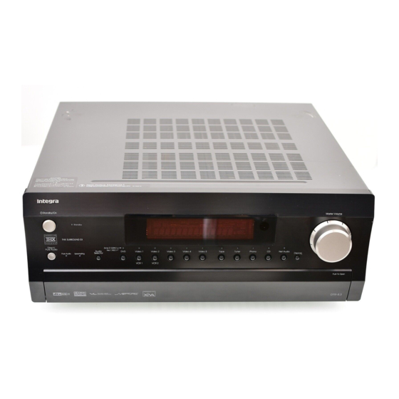
Page 10: Index Parts And Facilities
Index parts and facilities Here is an explanation of the controls and displays on the front panel of the DTR-8.3. Front panels Front door Push here to open the front door. -
Page 11: Front Panels
DTR-8.3 cannot be operated. Standby indicator [7, 30] Lights when the DTR-8.3 is in the standby state and when a signal is received from the remote controller. Audio Selector button [35] Press to select the type of audio input signal. -
Page 12: Front Panel Display
Index parts and facilities Tuning / , Preset / buttons [36, 37, 43] To tune into a radio station, press the Tuning / buttons. The tuner frequency is displayed in the front display and it can be changed in 50- kHz increments for FM and 10-kHz (or 9-kHz) increments for AM. -
Page 13: Rear Panels
DVD player, see page 18; to connect a DVD recorder, see page 20; and to connect a digital satellite tuner, see page 21. PRE OUT [23, 26, 29] To use the DTR-8.3 as a preamplifier, connect a power amplifier to this jack. ANTENNA [24, 25] These jacks are for connecting the FM indoor antenna and AM loop antenna that are supplied with the DTR-8.3. -
Page 14: Remote Controller
Index parts and facilities Remote controller Home menu – CONT LIGHT AV Amp (Select AV Amp on the Home menu) (page 1/4) MUTE – (page 2/4) (page 3/4) (page 4/4) - Page 15 Enter button to advance to the next item. Sleep button [34] Press to set the sleep function. The SLEEP button enables you to set the DTR-8.3 to turn off automatically after a specified time period. +/– buttons [34, 48] Select the speaker whose volume is to be adjusted using the CH Sel button and adjust the volume using the +/–...
-
Page 16: Connecting To Audio/Video Equipment
Connecting to Audio/Video equipment • Be sure to always refer to the instructions that came with the component that you are connecting. • Do not plug in the power cord until all connections have been properly made. • For input jacks, red connectors (marked R) are used for the right channel, white connectors (marked L) are used for the left channel, and yellow connectors (marked V) are used for video connection. -
Page 17: Connecting Your Audio Components
Connecting to Audio/Video equipment Here is an explanation of typical ways to connect various components to the DTR-8.3. There are many ways that any one component can be connected, and it is up to you to decide which method best fits your situation. The directions given here are only one option and should only be thought of as such. -
Page 18: Connecting Your Video Components
(composite) of the DVD or LD player to the DVD VIDEO IN jack of the DTR-8.3. Or if the DVD or LD player has an S video output jack, connect it to the DVD S VIDEO IN jack with an S video cable. Or if the device has component video outputs, connect them to one of the banks of COMPONENT VIDEO INPUT jacks on the DTR-8.3. - Page 19 VIDEO 1 VIDEO IN jack of the DTR-8.3 and connect the video input jack of the video cassette recorder to the VIDEO 1 VIDEO OUT jack of the DTR-8.3. Or if the video cassette recorder has S video input and output jacks, connect them to the VIDEO 1 S VIDEO IN and OUT jacks of the DTR-8.3...
- Page 20 (VIDEO 2) Using RCA video cables, connect the video output jack (composite) of the device to the VIDEO 2 VIDEO IN jack of the DTR-8.3 and connect the video input jack of the device to the VIDEO 2 VIDEO OUT jack of the DTR-8.3.
- Page 21 DTR-8.3. Or if the device has an S video output jack, connect it to the VIDEO 3 (or 4) S VIDEO IN jack of the DTR-8.3 using an S video cable. Or if the device has component video outputs, connect them to one of the banks of COMPONENT VIDEO INPUT jacks on the DTR-8.3.
-
Page 22: Connecting Speakers
Connecting speakers Before connecting the speakers, it is very important to place them properly for the optimum sound space for your listening pleasure. Be sure to refer to the instruction manuals that came with the speakers during placement and connection. Furthermore, be aware that for surround playback, the configuration and placement of your speakers are both very important. -
Page 23: Connecting Speakers
Caution: Connect only speakers with an impedance between 4 and 16 Ω to the DTR-8.3. If the impedance of even one speaker is between 4 and 6 Ω, be sure to set the speaker impedance setting accordingly (see page 44). -
Page 24: Connecting Antennas
Connecting antennas To use the tuner of DTR-8.3, it is necessary to prepare the supplied FM and AM antennas. • Adjustment and placement of the FM and AM antennas for better reception must be done while listening to a station broadcast. -
Page 25: Connecting An Fm Outdoor Antenna
Connecting antennas Connecting an FM outdoor antenna Make sure to follow the general rules given below: • Keep the antenna away from noise sources (neon signs, busy roads, etc.). • It is dangerous to put the antenna close to power lines. Keep it well away from power lines, transformers, etc. -
Page 26: Connecting The Remote Zone (Zone 2) Speakers
The room where the DTR-8.3 is actually located is referred to as the main room while the separate room is referred to as the remote zone (Zone 2). In addition, the IR IN/OUT terminal of the DTR-8.3 allows you to... -
Page 27: Operating Components Not Reached By The Remote Controller Signals (Ir In/Out)
In the cabinet The IR IN input allows you to control the DTR-8.3 from the remote zone (Zone 2) with the remote controller even though the remote zone may be on the other side of the building from the main zone. -
Page 28: Miscellaneous Connections
• If a component has two terminals, you can use either one to connect to the DTR-8.3. The other one can be used to daisy chain with another component. • With Integra/Onkyo DVD players, you can enter the pre-... -
Page 29: Connecting To Devices With Analog Multi Channel Output
Set the 12V TRIGGER terminal using the Setup menu: Input setup → 12V trigger (see page 52). When the DTR-8.3 is in the ZONE 2 mode, this terminal outputs at 12 V/100 mA. to White... -
Page 30: Connecting The Power
To change the display of the input source from TAPE to MD If you connected an MD recorder to the TAPE jack on the DTR-8.3, you can have “MD” appear when the TAPE source button is pressed. Changing the display: Press and hold down the TAPE source button until the display changes from TAPE to MD (approx. -
Page 31: Enjoying Music Or Videos With The Dtr-8.3
Enjoying music or videos with the DTR-8.3 Input source buttons Though the DTR-8.3 is often used to listen to the radio, it does not show you its true ability until it is used to play music or watch videos, DVDs, and the like. The DTR-8.3 has the latest and most state-of-the-art features to play back today’s technologies with the... -
Page 32: Changing The Listening Mode
Changing the listening mode To change the listening mode during playback, press the listening mode buttons. The functions of the buttons on the DTR-8.3 and those on the remote controller are the same. For more information on each listening mode, see pages 54 and 55. -
Page 33: Switching The Display
Switching the display While listening to or watching an input source, you can display the information regarding the type of source and signal being input by pressing the Display button on the DTR-8.3 or the remote controller. Remote controller DTR-8.3... -
Page 34: Adjusting The Brightness Of The Front Display
Enjoying music or videos with the DTR-8.3 Dimmer Adjusting the brightness of the front display You can adjust the brightness of the front display of the DTR-8.3 using the DIM button on the remote controller or Dimmer button on the DTR-8.3 front panel. -
Page 35: Changing The Audio Mode
Remote controller Audio Selector Auto (automatic detection): With this setting, the DTR-8.3 automatically detects whether the input signal is digital or analog. When a digital signal is not input, then the analog signal is played. This setting only appears if a digital input is selected for the Digital Input setting at Setup Menu →... -
Page 36: Listening To Radio Broadcasts
Listening to Radio Broadcasts FM Mode One of the features of the DTR-8.3 that is most frequently used is its ability to play FM and AM broadcast radio stations. The DTR-8.3 provides a number of listening modes perfect for listening to the radio and getting the most out of your audio system. -
Page 37: Presetting A Radio Station
• You can enter text names for any of the preset radio stations (see page 51). Preset Selecting a preset radio station 1. Press Tuner input source button on the DTR-8.3 or Tuner button on the remote controller. The front display should show the currently selected frequency. Memory 2. -
Page 38: Recording A Source
Recording a source To record the input source signal you are currently watching or listening to This method outputs to the audio and video outputs the currently selected input source signal. This method allows you to a signal while you are actually listening to or watching it. 1. -
Page 39: Recording The Video From One Source And The Audio From Another
Recording a source Recording the video from one source and the audio from another You can add the sound from one source to the video of another source to make your own video recordings. Below is an example of recording the sound from a compact disc player connected to CD IN and the video from a video camera connected to VIDEO 5 INPUT to video cassette tape in a video cassette recorder connected to the VIDEO 1 OUT jack. -
Page 40: Enjoying Music Or Videos In The Remote Zone
Enjoying music or videos in the remote zone Using the buttons on the DTR-8.3 1. Press the Zone 2 button on the DTR-8.3. 2. Select an input source. After pressing the Zone 2 button, you must press an input source button within 8 seconds. -
Page 41: Selecting An Input Source Using The Remote Controller
– Note: When the remote zone (Zone 2) speakers are connected to the pre- main amplifier that is connected to the ZONE 2 terminal of the DTR-8.3, adjust the volume for the remote zone at the pre-main amplifier. – CONT... -
Page 42: Setup Menu
When making the various settings required to configure your DTR-8.3 for optimum performance, you can either use the OSD Menu that appears on your television monitor or you can use the display on the front of the DTR-8.3. The OSD Menu is a settings menu that is displayed on your TV monitor. -
Page 43: Navigating Through The Setup Menu
You can change settings in the Setup Menu using the buttons on the front panel and on the remote controller. The buttons on the remote controller correspond to those on the DTR-8.3 as shown below. Button on remote controller Setup... -
Page 44: Hardware Setup
|ENTER|Quit:|SETUP| The settings within the Hardware Setup Menu will need to be made before you use your DTR-8.3 for the first time. Once you have selected one of the Hardware Setup menu items, the setting will not be displayed again when you enter the Basic Menu. To change the setting at a later date, select the Advanced Menu to display the Hardware Setup Menu. -
Page 45: Surr Back/Zone 2 Sub-Menu
Quit:|SETUP| Use this sub-menu when you have a remote control sensor connected to the IR IN terminal. The setting in this sub-menu tells the DTR-8.3 whether the remote control sensor is being used for operation of the DTR-8.3 in the main zone or the remote zone (Zone 2). -
Page 46: Speaker Setup
Speaker Setup 1. Speaker Setup Menu After you have installed the DTR-8.3, connected all the components, and determined the speaker layout, it is now time to perform the settings in the Speaker Setup Menu for the optimum sound acoustics for your environment and speaker layout. -
Page 47: Speaker Distance Sub-Menu
Speaker Setup f. Crossover This setting allows you to set the crossover frequency for your speaker system. The crossover frequency is the minimum frequency delivered to a speaker and can be set to 40 Hz, 60 Hz, 80 Hz (THX), 100 Hz, or 120 Hz. -
Page 48: Level Calibration Sub-Menu
(3) Press the CH Sel button again. The DTR-8.3 will now emit the pink noise from the front right speaker. -
Page 49: Input Setup
This menu allows you to make the various settings concerning the signals input from the various input sources that you use with the DTR-8.3. The settings made in this menu are valid for the input source that is currently selected with the input source buttons at the front panel and, therefore, these settings are made separately for each input source. -
Page 50: Multichannel Setup Sub-Menu (When Net Audio Is Not Selected As The Input Source)
In such cases, try playing the source in the “DTS” selected. • The DTS indicator on the DTR-8.3 lights while a DTS source is played. When playback finishes and the DTS signal transmission stops, the DTR-8.3 remains in DTS mode and the DTS indicator remains lit. -
Page 51: Video Setup Sub-Menu
Input Setup 2-3. Video Setup Sub-menu Advanced Menu 2.Input Setup Input:DVD 2-3.Video Setup Input:DVD a.Video :DVD b.Component Video :INPUT1 Quit:|SETUP| a. Video This setting allows you to match the audio from one component with the video from another. Therefore, you can set a video source to be displayed while the audio from another input source is heard. -
Page 52: Intellivolume Sub-Menu
The Intelli Volume can be adjusted between –12 and +12 decibels. 2-6. Listening Mode Preset Sub-menu With the DTR-8.3, you can set a different listening mode for each different signal type that comes from each input source. For example, if your DVD player also plays compact discs and the DVD video signal is Dolby Digital and the compact disc signal is PCM, then you can set a different listening mode for each. - Page 53 Input Setup Relationship between input source and listening mode Listening modes marked with the “G” can be selected. For columns that list a number of listening modes, the display will correspond to the format of the signal from the source media. Input source signal (display) a.
- Page 54 Input Setup Input source signals a. Analog/PCM Analog sources consist of LP records, FM and AM broadcasts, cassette tapes, and the such. PCM (Pulse Code Modulation) is one form of digital audio signals and is recorded directly onto compact discs and DVDs without compression. b.
- Page 55 Dolby web site at http://www.dolby.com. The DTR-8.3 can play the 5.1-channel sources in THX surround EX mode, even if the source is not encoded in Dolby Digital Surround EX format. In this case, the sound actually output from the surround back channels depends on the source and may not fit your tastes.
-
Page 56: Audio Adjust
Audio Adjust 3. Audio Adjust Menu Set the various parameters for the sound signals. Advanced Menu 3.Audio Adjust 1.Tone Control 2.Surround Speakers 3.Sound Effect 4.Delay 5.LFE Level 6.Mono 7.Theater-Dimensional 8.Surround Advanced Menu 3.Audio Adjust 9.THX 10.Mono Movie 11.Enhanced 7 12.Orchestra 13.Unplugged 14.Studio-Mix 15.TV Logic... -
Page 57: Sound Effect Sub-Menu
Audio Adjust 3-3. Sound Effect Sub-menu This sub-menu is used to turn on and off the various sound effects available with the DTR-8.3. Setting Values a. Re-EQ On, Off b. Upsampling On, Off c. Subwoofer On, Off (Analog/PCM) d. Late Night Off, Low, High a. -
Page 58: Lfe Level Sub-Menu
Some films have been transferred to video without such a high-frequency rolloff, and thus sound overly bright and hissy. The DTR-8.3 includes this “Academy filter,” which is based on contemporary playback practices for such films over wide-range systems. -
Page 59: Surround Sub-Menu
Audio Adjust 3-8. Surround Sub-menu This sub-menu provides various settings for modifying the plain Dolby Digital, DTS, and Pro Logic II Surround listening modes. The settings that can be set are shown in the table below. Setting Values a. Surr Mode Pro Logic II Movie (Analog/PCM) Pro Logic II Music... -
Page 60: Enhanced 7/Orchestra/Unplugged/Studio Mix /Tv Logic Sub-Menu
Audio Adjust 3-9. THX Sub-menu This sub-menu allows you to set the settings that will be enabled when the THX listening mode is selected. The settings available are shown in the table below. Setting Values a. Re-EQ (THX) Off, On b. - Page 61 Audio Adjust Settings possible for each listening mode (3-1. 3-2. 3-3. Sub-menu) Setting 3-1. Tone Control a. Bass b. Treble Listening mode Mono Direct/Pure Audio Stereo Theater-Dimensional Dolby EX DTS-ES Matrix 6.1 DTS-ES Discrete 6.1 DTS 96/24 Dolby Digital Dolby Pro Logic II DTS-ES Neo:6 THX Cinema (PLII) THX Cinema (Neo:6)
-
Page 62: Preference
“Off.” d. Power On Volume This sets a designated volume for which the DTR-8.3 will be set to every time that the power is turned on. This prevents the DTR-8.3 from suddenly outputting very loud sounds if it is turned on while it is set to an extremely high volume. -
Page 63: Headphones Level Sub-Menu
(Australian model only) The default setting is “Auto,” which means that the television format is detected and automatically set by the DTR-8.3. However, if you know the correct format, you can use this setting to choose either PAL or NTSC so that no time is wasted on detection. -
Page 64: Remote Controller
Using the Remote Controller Adjust the Settings Most of the remote controller’s features can be set to your own needs. 1. Touch and hold the remote controller icon for a few seconds. The first setup panel appears. You can see the second and third setup panel by using the scroll buttons. -
Page 65: Working With Modes
Using the Remote Controller The remote controller is preprogrammed to work with all equipment that recognizes NEC infrared codes. This includes all Integra/Onkyo devices. What makes the remote controller so powerful is the ability to extend its functionality in multiple ways like programming additional functions, adding supplementary devices, recording macros and customizing the interface as it suits you best. -
Page 66: Selecting A Device
In the Home menu, you find buttons for the most common video and audio devices. These buttons are preprogrammed to work with popular devices made by Integra/Onkyo. If you have devices of other manufacturers that do not respond to your remote controller, you can program your remote controller using your original remote controllers (see “Programming Buttons”... -
Page 67: Define The Brand Of Your Device
CDR, MD, HDR, P’jector, LD When you select these devices, the preset RC codes for operating Integra/Onkyo’s devices are used, and the operation buttons for the device appear on the screen. You can use the preset RC codes only when the Integra/Onkyo’s device you selected and Integra/ Onkyo’s amplifier or receiver are connected using... - Page 68 Define the Brand of Your Device Note: In case, your brand is not displayed in the list of brands, Try Search mode. See “Defining brands by searching” on page 69. 5. Select your brand from the list. The selected brand will be highlighted. The Search button switches into Next.
-
Page 69: Defining Brands By Searching
Define the Brand of Your Device Defining brands by searching You can use Search mode to find the matching RC codes for your device when • your brand is not displayed in the list of brands, • you selected your brand, but you do not know which code set to select. -
Page 70: Programming Buttons
Programming Buttons You can program the remote controller commands by transmitting infrared signals from your existing remote controls to the remote controller’s learning eye. To do this, place the remote controller and the device’s remote controller on a flat surface, 6 to 8 inches(15 to 20 cm ) apart. -
Page 71: Programming Device Items
Programming Buttons Programming device items Note: When you program a command to a device item, this command is automatically assigned to the corresponding button in the Home menu. 1. Make sure the device tab is active. The device tab is active when the name of a device is displayed. 2. -
Page 72: Labeling Buttons And Menu Items
Labeling Buttons and Menu Items The following elements can be labeled: control panel buttons, Device menu items, macros, macro groups and Left/Right buttons. You cannot label Home menu buttons directly. You have to label them by using the Device menu (see below) Labeling a button 1. -
Page 73: Adding And Moving Devices
Adding and Moving Devices Adding devices If you have a device that is not provided in the Device menu, you can add it to the remote controller. You cannot add devices to the Home menu directly. You have to add them by using the Device menu. -
Page 74: Delete And Restore
Delete and restore Delete You can delete control panel buttons and functions associated with a direct-access or a Left/Right button. You can also delete Device menu items and Macro menu items. Home menu buttons cannot be deleted directly. You have to delete them via the Device menu. -
Page 75: Recording Macros And Setting Timers
Recording Macros and Setting Timers A macro enables you to send a sequence of IR commands using one single button. (USA & Canadian models) By setting a time, you can activate a device at the time you prefer. See page 76. Note: To record a macro or to set a timer, there must be at least one macro group or timer group in the Macro menu. -
Page 76: Setting Timers
Recording Macros and Setting Timers 3. Use the arrow buttons to move the delay to the right place. 5. Press the Left button to close the macro. A confirmation screen appears, which allows you to save or cancel the macro. 6. -
Page 77: Using The Remote Controller With Radio Frequency (Usa & Canadian Models Only)
Using the remote controller with Radio Frequency (USA & Canadian models only) Warning: To use the remote controller with radio frequency (RF), you need an RF Receiver, which is not included in package. By default, the remote controller uses infrared (IR) signals to operate devices. -
Page 78: Choosing Another Channel
Using the remote controller with Radio Frequency (USA & Canadian model only) Changing the Extender ID 1. Make sure the Extender ID button is active. The button is active when the button label is white. 2. Press the + and – action buttons to change the Extender ID. The remote controller offers 16 Extender ID’s. -
Page 79: Additional Information
Additional information ChadEdit If you want to personalize your remote controller even more, beyond its standard programming features, ChadEdit is the tool for you to use. ChadEdit is the remote controller’s companion software that you can download from http:// www.onkyousa.com www.integrahometheater.com. -
Page 80: Faq
Can I program a button to execute more than one command? No, you can not. However, you can create a macro to execute a sequence of commands (see page 73, 75). How do I program source switching? See “Programming device items” on page 71. How can I edit, label or delete buttons on home panels? You can do this via the Device menu items. -
Page 81: Overview Of Symbols
Overview of Symbols :Pause :Stop :Normal run; normal speed :Normal run; normal speed :Fast run; fast speed :Fast run; fast speed :Slow run; slow speed :Slow run; slow speed :Eject :Recording, general :Key :Navigate :Still mode :Tape running direction :Next track :Previous track :Fast forward to index :Rewind to index... -
Page 82: Troubleshooting Guide
If a problem occurs while you are using the remote controller, first try to operate the controls on the front panel of the DTR-8.3 to make sure that it is not due to a malfunction (or worn out batteries) in the remote controller. -
Page 83: Video And Audio
Troubleshooting guide VIDEO and AUDIO Desired picture does not appear. • Improper connection. © Check connections. Insert the plugs and connectors completely (see pages 16 to 29). • Video Setup Sub-menu settings are incorrect. © Check settings at Setup Menu → Input Setup Menu → Video Setup Sub-menu (see page 51). -
Page 84: Remote Controller
Remote controller error messages © If one of the following error messages occurs, please contact your dealer or the Integra/Onkyo authorized service station: © Can not open configuration file © Configuration file error © No configuration file found ©... -
Page 85: If One Of The Messages Shown Below Appears
* To reset the surround mode and other settings to the factory default settings, hold down the VIDEO 1 button with the DTR- 8.3 turned on and then press the STANDBY/ON button. “CLEAR” appears in the front display and the DTR-8.3 enters the standby state. -
Page 86: Specifications
Specifications AMPLIFIER SECTION Continuous average power output (FTC) All channels: 110 W per channel min. RMS at 8 Ω, 2 channels driven from 20 Hz to 20 kHz with no more than 0.08% total harmonic distortion. 145 W min. RMS at 6 Ω, 2 channels driven from 1 kHz with no more than distortion. - Page 87 Specifications REMOTE CONTROLLER Model: USA & Canadian models: USR-5 Australian models: USR-5RF High-resolution (320 × 240) liquid crystal Hardware: display (LCD) with contrast control Large touchscreen Seven programmable direct-access buttons Backlighting for LCD and direct-access buttons Infrared sending and learning eyes 3-wire (RS232) serial port connector Software: Dynamic, animated interface...
- Page 88 Integra Division of ONKYO U.S.A. CORPORATION 18 Park Way, Upper Saddle River, N.J. 07458, U.S.A. Tel: 201-785-2600 Fax: 201-785-2650 http://www. integrahometheater.com Integra Division of ONKYO CORPORATION Sales & Product Planning Div. : 2-1, Nisshin-cho, Neyagawa-shi, OSAKA 572-8540, JAPAN Tel: 072-831-8111 Fax: 072-831-8124...
-
Page 89: System Requirements
DTR-8.3 Features The DTR-8.3 is a network audio client that is connected via a LAN to an Audio Network Server with Net-Tune System Protocol and allows you to enjoy music files saved on the server, as well as Internet radio, from anywhere in your home. - Page 90 Connecting the DTR-8.3 to your Ethernet Network Plug one end of an Ethernet CAT-5 cable into the port on the backside of the DTR-8.3 and the other end into the gateway. Internet Audio Network Server Modem To the WAN side...
-
Page 91: Enjoying Internet Radio
You can return to the previous step by pressing the 7. Press the Select button. Buffering starts with the following message displayed. When the buffering completes, the DTR-8.3 starts playback of the broadcast. Note: If you are connected to the Internet via a slow link (such as a dial-up connection) rather than a broadband link (via an xDSL or cable modem), you may not be able to enjoy Internet radio as you expect or at all. - Page 92 It may take a few minutes. 2. Turn on the DTR-8.3. When you connect the DTR-8.3 to the network first time, it will be connected to the server found first. 3. Press the Net Audio button on the main unit.
- Page 93 Repeat All: Repeats the tracks in the currently selected mode. Repeat Off: Repeat mode is disabled. You can operate the DTR-8.3 when playing and stopped. I Selecting a track list: You can use the music file data saved on the Audio Network Server to select which tracks to play.
-
Page 94: Configuring Various Settings
OSD. Network Setup Menu Before you can use the DTR-8.3 to play music contained in the music library on the Audio Network Server and listen to Internet radio, you must correctly configure the DTR-8.3’s network settings so that it can connect to your LAN and the Internet. - Page 95 Also, you can use this menu to manually configure network settings. Referring to the documentation from your ISP, enter the IP address and subnet mask assigned to your DTR-8.3 as well as the IP addresses of the default gateway and DNS server.
-
Page 96: Appendix Troubleshooting Guide
If this does not resolve the problem, turn off the power of the Audio Network Server and turn it on again. • The NTSP Port setting on the DTR-8.3 differs from that of the Audio Network Server. © Go to “5-4.Client Setup Sub-menu”, select “c.NTSP Port”, then set the same value as used for the Audio Network Server.
Need help?
Do you have a question about the DTR-8.3 and is the answer not in the manual?
Questions and answers