Cino FuzzyScan MBC6890 Series User Manual
Bluetooth bar code imager
Hide thumbs
Also See for FuzzyScan MBC6890 Series:
- User manual (54 pages) ,
- Quick reference instructions (20 pages)
Table of Contents
Advertisement
Quick Links
Advertisement
Table of Contents

Related Manuals for Cino FuzzyScan MBC6890 Series


Summary of Contents for Cino FuzzyScan MBC6890 Series
-
Page 2: Regulatory Information
All registered and unregistered trademarks used herein are the exclusive property of their respective owners. Copyright Copyright 1998-2005 PC Worth Int'l Co., Ltd. Copyright 1998-2005 Cino Group Regulatory Information This device complies with Part 15 of the FCC Rules. Operation is subject to the following conditions: This device may not cause harmful interference. -
Page 3: Table Of Contents
Table of Contents International Edition, Rev. B Getting Started ... Getting Familiar with HC8590 Cordless Imager... Decide the Radio Link Mode ..4 Preparations Before Using ..5 Using HC8590 Cordless Imager ... Using HC8590 with DB100 Smart Cradle ... Using HC8590 via Bluetooth SPP Service ... -
Page 4: Getting Started
Getting Started Thank you for choosing HC8590 series Bluetooth Cordless Linear Imager. The HC8590 series cordless imagers are designed with remarkable optical architecture and innovative functionality. By incorporating Bluetooth 1.2 wireless technology which operates on the → 2.4 GHz ISM band, the HC8590 series is compatible with most popular Bluetooth-enabled devices, such as PCs, laptops and PDAs, and so on. -
Page 5: Getting Familiar With Hc8590 Cordless Imager
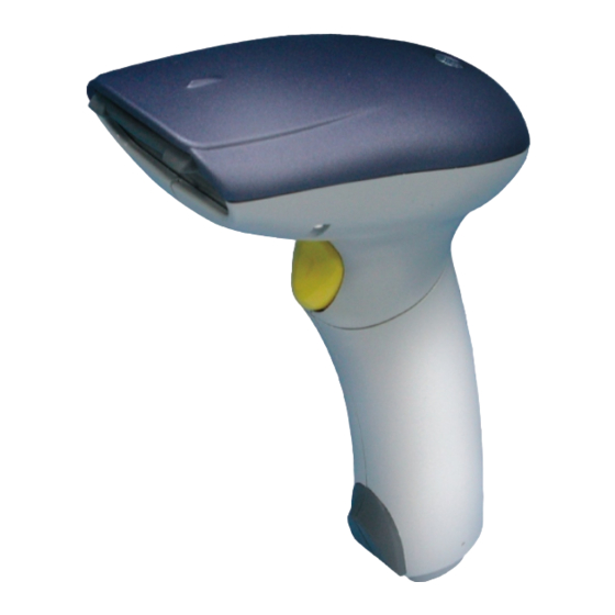
Getting Familiar with HC8590 Cordless Imager HC8590 Bluetooth Cordless Imager Scan Window Reset Button Trigger Unlock Hole Imager LED Buzzer Hand Strip Hole Battery Tank Battery Cover End Cap Battery Cover Lock Internal Connector HC8590 User’s Guide... - Page 6 DB100 Smart Cradle / DA100 Charging Cradle Left LED Right LED - - Reserved Reserved Middle LED [ DB100 ] Connection Status Indication [ DA100 ] Power On Indication [ DB100 ] Multi Function Button [ DA100 ] Reserved [ DB100 ] Universal Legacy Output Port DC Power Jack [ DA100 ]...
-
Page 7: Decide The Radio Link Mode
Decide the Radio Link Mode The HC8590 provides three (3) different radio link modes including Pair Mode, SPP Slave and Master Modes. You may choose the suitable one to implement your desired cordless scanning solution. …… Note for Installation Engineer The factory default setting of HC8590 is in “Uninstall State”... -
Page 8: Preparations Before Using
Preparations Before Using (1) Have a remote Bluetooth system ready to work. (2) Open the battery cover then place the rechargeable batteries into the battery tank. Please make sure the batteries are placed in correct direction. (Do not charge non-rechargeable batteries, as it may cause explosion.) (3) Close the battery cover and insert the end cap. - Page 9 HC8590 User’s Guide...
-
Page 10: Using Hc8590 Cordless Imager
Using HC8590 Cordless Imager The HC8590 cordless imager has to establish communication with a host system for data transmission. There are several ways for connecting HC8590 to the host system: By using with the DB100 smart cradle, through one of legacy output interfaces such as PS/2 keyboard wedge, RS232 serial interface, USB keyboard interface and USB serial interface and so on. -
Page 11: Using Hc8590 With Db100 Smart Cradle
Using HC8590 with DB100 Smart Cradle The HC8590 works with DB100 smart cradle to perform just as it is directly wire-connected to a host PC through one of legacy interfaces such as PS/2 keyboard wedge, RS232 serial, USB keyboard and USB serial. - Page 12 The Installation Procedure Please refer to following procedures for connecting HC8590 to a host system by using with DB100 smart cradle: Make sure that batteries are fully charged and placed into HC8590. You may refer to the Section “Preparations Before Using”...
- Page 13 Scan “Pair Mode” barcode command. The imager gives 2 short beeps, and imager LED gives red blinks. Pair Mode Command After scanning the “Pair Mode” barcode command, the imager will enter into “Sleep State”, if the imager is not placed on the cradle within 10 seconds.
- Page 14 Host Interface Quickset Command PC/AT, PS/2 Keyboard Wedge Quick Set Command Keyboard Replacement Quick Set Command RS-232 Serial Interface Quick Set Command USB Keyboard Interface Quick Set Command USB Serial Interface Quick Set Command If the USB serial interface is selected, you have to install the USB virtual COM driver in your host system before using the imager.
- Page 15 Enable Out-of-Range Scanning Under normal mode (default setting), when the radio link between the HC8590 and the host system is built, the HC8590 transmits each scanned data right after scanning the bar code label. However, the HC8590 can not scan any bar code data while losing its connection with the remote host system due to out of range.
- Page 16 Activate Batch Mode You can activate batch mode to have HC8590 stored scanned data without building the connection with a remote host system. To enable this function, please scan “Enter Batch Mode” quick set command. When a bar code is saved successfully, a good read beep sounds and the LED flashes green.
-
Page 17: Using Hc8590 Via Bluetooth Spp Service
Using HC8590 via Bluetooth SPP Service Bluetooth wireless technology works on global RF standards, which operates on the 2.4 GHz ISM band. This enables wireless connectivity between the remote Bluetooth devices and the host computer built-in Bluetooth radio, such as PCs, laptops and PDAs, etc. Usually, all actions between a program installed on your computer and a remote Bluetooth device are carried out by the Bluetooth services. -
Page 18: Establish Spp Master Connection
Establish SPP Master Connection While configuring the HC8590 to be used in SPP Master mode, the Imager will initiate the connection to the remote Bluetooth host system. The special-designed Auto Reconnecting feature is provided by HC8590 under this mode. If the radio link is lost, the automatic radio re-build process will be activated immediately. - Page 19 Scan the “SPP Master Mode” barcode command, the imager gives 2 short beeps and imager LED gives red blinks. SPP Master Mode Quick Set Command After scanning the “SPP Master Mode” barcode command, the imager will enter “Sleep State”, if the radio link is not built within 1 minute.
- Page 20 Enable Out-of-Range Scanning Under normal mode (default setting), when the radio link between the HC8590 and the host system is built, the HC8590 transmits each scanned data right after scanning the bar code label. However, the HC8590 can not scan any bar code data while losing its connection with the remote host system due to out of range.
- Page 21 Activate Batch Mode You can activate batch mode to have HC8590 stored scanned data without building the connection with a remote host system. To enable this function, please scan “Enter Batch Mode” quick set command. When a bar code is saved successfully, a good read beep sounds and the LED flashes green.
-
Page 22: Establish Spp Slave Connection
Establish SPP Slave Connection While configuring the HC8590 to be used in SPP Slave mode, the imager will only wait for the connection request issued by the remote Bluetooth master system to establish the radio link. Once the pre-built radio link is lost, user has to re-build the radio link manually. - Page 23 “00000000”. Double click the “CINO HC8590” on the found Bluetooth devices. You will see the “CINO SPP” service on the imager. Double click the “CINO SPP” service to establish the connection between HC8590 and remote Bluetooth master system. The HC8590 imager gives 4 beeps in ascending tone to indicate the radio link built.
- Page 24 Enable Out-of-Range Scanning Under normal mode (default setting), when the radio link between the HC8590 and the host system is built, the HC8590 transmits each scanned data right after scanning the bar code label. However, the HC8590 can not scan any bar code data while losing its connection with the remote host system due to out of range.
- Page 25 Activate Batch Mode You can activate batch mode to have HC8590 stored scanned data without building the connection with a remote host system. To enable this function, please scan “Enter Batch Mode” quick set command. When a bar code is saved successfully, a good read beep sounds and the LED flashes green.
-
Page 26: Operations And Indications
Operations and Indications The HC8590 has two indicators, LED and buzzer. They will provide various indications depending on the actual operating conditions and states. you may obtain necessary information to understand all details by referring to following sections described in this Chapter, including: Useful Tips for Field Operation HC8590 Major Sates During Operation HC8590 Indications... -
Page 27: Useful Tips For Field Operation
Useful Tips for Field Operation Please refer following four useful tips for your field operation : 4 descending-tone beeps When you heard the special 4 descending-tone beeps, it means the imager has lost the radio link already. This condition mostly happens when you go out of the radio covering range. -
Page 28: Hc8590 Major States During Operation
HC8590 Major States During Operation Once the scanning system is properly set up, HC8590 will always be under one of the following Operational States: Indications State & Actions Beeper 1. Radio Uninstall State Radio link not installed alternating Install the radio link red &... -
Page 29: Hc8590 Indications
HC8590 Indications Indications Descriptions Beeper “Sleep State”, or “Batteries no power”, or No batteries inside “Under Configuration” steady red “Radio Uninstall State” alternating red & green blinks “Radio Connected” (Ready to scan barcode) 1 green blink at regular interval “Radio Disconnected” 1 red blink at regular interval “Battery power low”... - Page 30 HC8590 Indications (Continued) Indications Descriptions Beeper Configuration fail 3 beeps 3 red blinks “Good Read” beep 1 good read beep 1 green blink Receiving ACK signal from smart cradle or 1 ACK beep 1 green blink host PC Power on indication 1 green blink power-on reset beeps...
-
Page 31: Cradle Indications
Cradle Indications : Reserved Right LED : Reserved Left LED Middle LED : DB100 - Connection status indication DA100 - Power on Indication Middle LED of DB100 Smart Cradle Indications Descriptions Beeper “Sleep State”, or “Battery no power”, or No battery inside Steady red “Under Configuration”... -
Page 32: Configure Hc8590 Cordless Imager
Configure HC8590 Cordless Imager The FuzzyScan bar code commands are specially designed for field programming convenience. All HC8590 series cordless linear imagers can take this way to make detailed configuration. Before configuring your imager, please understand the command structure and programming procedures in advance. The bar code commands include System Command, Family Code and Option Code for programming purpose. -
Page 33: Programming Procedures
Programming Procedures As you scan the bar code command to select the desired parameters, all the final selected configurations will be stored in the FuzzyScan’s internal non-volatile memory. If you power off the unit, the imager retains all programming options. You need not re-program the FuzzyScan if you want to keep the existing configurations for the next power on. -
Page 34: Host Interface Selection
Host Interface Selection Command P.C. Parameter Selection Option IBM PC/XT keyboard wedge IBM PC/AT, PS/2 series keyboard wedge Compaq, HP Vectra PC keyboard wedge Host Interface Apple ADB keyboard wedge Selection Standard/TTL RS232 peer-to-peer serial interface Standard/TTL RS232 serial wedge interface Wand emulation interface Pseudo RS232 serial interface (3-wire TTL level) PC/AT, PS/2 keyboard replacement... -
Page 35: Operation Control
Operation Control 1Command P.C. Parameter Selection Option Buzzer tone - mute Buzzer tone - low Buzzer Tone Buzzer tone - medium Adjustment Buzzer tone - high Buzzer tone - extremely high Good-read beep before data transmission Good-read beep after data transmission Power-on beep No power-on beep Acknowledgement beeping tone - mute... -
Page 36: Symbology Reading Control
Symbology Reading Control User Defined Symbol ID Command P.C. Parameter Selection Option Option Code 128 (default=B) (1 Character) UCC/EAN-128 (default=C) (1 Character) UPC-A (default=A) (1 Character) Symbol ID - 1 character - EAN/JAN/CAN-13 (default=F) (1 Character) Codabar/NW-7 (default=D) (1 Character) Code 39/Code 32 (default=G) (1 Character) Code 93 (default=H) - Page 37 Codabar & NW-7 Setting Command P.C. Parameter Selection Option Select Codabar standard format Select Codabar ABC format Select Codabar CLSI format Codabar Setting Select Codabar CX format Disable start/stop symbol transmission Enable ABCD/ABCD start/stop symbol transmission Enable abcd/abcd start/stop symbol transmission Enable ABCD/TN*E start/stop symbol transmission Enable abcd/tn*e start/stop symbol transmission Disable check digit verification...
- Page 38 Code 25 & German Post Setting Command P.C. Parameter Selection Option Select any Code 25 Select Standard/Industrial 2 of 5 only Select Matrix 2 of 5 only Code 25 Setting Select Interleaved 2 of 5 only Select Interleaved 2 of 5 S Code only Select IATA only Select China Postal Code only Disable check digit verification...
- Page 39 HC8590 User’s Guide...
- Page 40 MSI/Plessey Setting Command P.C. Parameter Selection Option Select MOD 10 check digit Select MOD 10-10 check digit Select MOD 11-10 check digit MSI/Plessey Setting Disable check digit transmission Enable 1-check digit transmission Enable 2-check digit transmission Default (04) 01-Maximum (2 digits) MSI/Plessey Minimum Length Default (98)
- Page 41 HC8590 User’s Guide...
-
Page 42: Keyboard Interface Control
Keyboard Interface Control Command P.C. Parameter Selection Option USA (QWERTY) France (AZERTY) Germany (QWERTZ) Language Setting United Kingdom - UK (QWERTY) Canadian French (QWERTY) Spain (QWERTY) Sweden/Finland (QWERTY) Portugal (QWERTY) Norway (QWERTY) Latin America (QWERTY) Italy (QWERTY) Netherlands (QWERTY) Denmark (QWERTY) Belgium (AZERTY) Switzerland-Germany (QWERTY) Iceland (QWERTY) -
Page 43: Serial Interface Control
Serial Interface Control Command P.C. Parameter Selection Option Disable STX/ETX transmission Enable STX/ETX transmission STX/ETX Control None TAB (09H) CR (0DH) SPACE (20H) LF (0AH) EOT (04H) Record Suffix CRLF (0D0AH) User defined character (1 character : 00~7F) None (free running mode) RTS/CTS (hardware handshaking) Handshaking Protocol ACK/NAK (software handshaking) -
Page 44: Wand Emulation Control
Wand Emulation Control Command P.C. Parameter Selection Option High level (5Vdc) on Bar (low level on Space) Low level (0Vdc) on Bar (high level on Space) Output Polarity High Level (5 Vdc) Low Level (0 Vdc) Initial Signal State 10 mseconds 30 mseconds 15 mseconds 50 mseconds... -
Page 45: Condensed Datawizard
Preamble. Symbology ID Transmission To enable the Symbology ID Transmission, the “CINO Symbology ID” or “AIM Symbology ID” will be added into the transmitted data. It is very helpful for applications to identify the specific bar code by symbology ID. - Page 46 Preamble, Postamble, Data Length Setting Command P.C. Parameter Selection Option None 1-15 characters [00-7F], [FIN] Preamble None 1-15 characters [00-7F], [FIN] Postamble Disable Enable 2-digits data length transmission If data length exceeds 99, 3-digit data length will be Data Length transmitted Transmission Data Formatter Setting...
- Page 47 Enable prefix CINO symbology ID Enable suffix CINO symbology ID Symbology ID Transmission Enable both prefix and suffix CINO symbology ID Enable prefix AIM symbology ID Enable suffix AIM symbology ID Enable both prefix and suffix AIM symbology ID Symbology ID Table :...
- Page 48 Select a Bar Code Symbology You can select one or all types of bar code symbologies to use Condensed DataWizard for advanced transmission arrangement. If you scan “00” to select all types, the HC8590 will arrange all incoming data to meet your pre-defined format. If you want to select only one type bar code, please select one of the option code listed below.
- Page 49 Programming Procedure D ata Verifier 【 】 Scan “Program” to enter the programming mode. Scan “Verifier Control” and set bar code symbology to “08” (Interleaved 2 of 5). Scan “Identified Data Length” and set the length to “16”. Scan “1 Identified Character”...
-
Page 50: Appendix
Appendix This appendix provides most useful supplementary information for following topics: Keyboard Function Code Table HEX/ASC Input Shortcut Barcode System Commands Option Codes and System Commands HC8590 User’s Guide... -
Page 51: Keyboard Function Code Table
Keyboard Function Code Table ANSI ASCII Key Function No. ANSI ASCII Key Function 00H RESERVED 10H F7 01H CTRL (Left) 11H F8 02H ALT (Left) 12H F9 03H SHIFT 13H F10 04H CAPS LOCK 14H F11 05H NUM LOCK 15H F12 06H ESC 16H INS (Insert) (Edit) 07H F1... -
Page 52: Ascii Input Shortcut
ASCII Input Shortcut To set the user definable configurations of HC8590 via programming menu, the HC8590 may ask you to scan your desired ASCII value in HEX form. You have to refer to the “HEX/ASCII Reference Table” for details. Example : If you want the scanned data output leading with a Dollar Sign, you have to set the “Preamble”... -
Page 53: Barcode System Commands
Barcode System Commands PROGRAM END (EXIT) System Information List Factory Default Setting PowerTool Host Link Enter Batch Mode Exit Batch Mode... - Page 54 HC8590 User’s Guide...
- Page 55 Barcode System Commands Host Interface Setting Radio Link Setting PC/AT, PS/2 Keyboard Wedge Quick Set Command Uninstall Keyboard Replacement Quick Set Command Pair Mode RS232 Serial Interface Quick Set Command SPP Slave Mode USB Keyboard Interface Quick Set Command SPP Master Mode USB Serial Interface Quick Set Command Paging Command...
-
Page 56: Barcode Option Codes
Barcode Option Codes PROGRAM FIN (Finish) END (Exit) HC8590 User’s Guide... - Page 57 DOC NO : YMAUA 3 0 0 1 0 0 0 0 0 0...
Need help?
Do you have a question about the FuzzyScan MBC6890 Series and is the answer not in the manual?
Questions and answers