
Subscribe to Our Youtube Channel
Related Manuals for GRASS VALLEY Profile XP PVS1000


Summary of Contents for GRASS VALLEY Profile XP PVS1000
- Page 1 Profile XP PVS SERIES MEDIA PLATFORMS Service Manual 071-8291-01 JULY 2004 the mos t watched worl dwide...
- Page 2 Broadcast and Media Solutions, Inc., P.O. Box 59900, Nevada City, California 95959-7900 Trademarks Grass Valley, Profile, and Profile XP are either registered trademarks or trademarks of Thomson Broadcast and Media Solutions, Inc. in the United States and/or other countries. Other trademarks used in this document are either registered trademarks or trademarks of the manufacturers or vendors of the associated products.
-
Page 3: Grass Valley Product Support
Grass Valley Product Support To get technical assistance, check on the status of problems, or report new problems, contact Grass Valley Product Support via e-mail, the Web, or by phone or fax. Web Technical Support To access support information on the Web, visit the product support Web page on the Grass Valley Web site. - Page 4 Product Support Profile XP Service Manual 23 July 2004...
-
Page 5: Safety Summaries
Safety Summaries General Safety Summary Review the following safety precautions to avoid injury and prevent damage to this product or any products connected to it. Only qualified personnel should perform service procedures. While using this product, you may need to access other parts of the system. Read the General Safety summary in other system manuals for warnings and cautions related to operating the system. -
Page 6: Safety Terms And Symbols
Safety Summaries Battery To avoid damage, replace only with the same or equivalent type Replacement recommended by the circuit board manufacturer. Dispose of used battery according to the circuit board manufacturer’s instructions. Safety Terms and Symbols Terms in This These terms may appear in this manual: Manual WARNING: Warning statements identify conditions or practices that can result in personal injury or loss of life. -
Page 7: Laser Compliance
Certifications and Compliances Canadian Certified Canadian approval includes the products and power cords appropriate for Power Cords use in the North America power network. All other power cords supplied are approved for the country of use. FCC Emission This equipment has been tested and found to comply with the limits for a Control Class A digital device, pursuant to Part 15 of the FCC Rules. - Page 8 Safety Summaries Laser Safety Laser safety in the United States is regulated by the Center for Devices and Radiological Health (CDRH). The laser safety regulations are published in the “Laser Product Performance Standard,” Code of Federal Regulation (CFR), Title 21, Subchapter J. The International Electrotechnical Commission (IEC) Standard 825, “Radiation of Laser Products, Equipment Classification, Requirements and User’s Guide,”...
-
Page 9: Table Of Contents
Contents Grass Valley Product Support ..................... 3 Safety Summaries ......................... 5 Preface ............................13 About this manual ......................13 Organization of the manual ................... 13 Related documentation ....................14 Product description ......................15 Standard accessories....................16 Profile XP Media Platform features ................17 Features common to all media platforms .............. - Page 10 Contents Audio problems related to SDI board ................45 Audio problems related to Audio board ................. 46 Correcting common audio problems .................. 48 Chapter 5 Troubleshooting timecode problems Checking NetCentral messages..................52 Correcting common timecode problems ................52 Chapter 6 Troubleshooting storage system problems Checking NetCentral messages –...
- Page 11 Contents Removing the system disk, floppy disk, or CD-ROM drive ........91 Installing a new system disk or restoring a corrupt system disk .......91 Removing the power supplies...................94 Internal parts removal....................95 Removing the top cover ....................95 Removing and installing plug-in circuit boards ............96 Removing the processor board.................97 Removing the air chamber..................97 Removing the standby/on switch and fault LED ............98...
- Page 12 Contents Triggering Profile XP GPI outputs ................145 Making settings for a Profile XP system ..............146 Profile log tools.........................147 Viewing Profile logs with WinTail.................147 Log Capture Tool......................147 Profile XP diagnostics ......................151 Starting Profile XP diagnostics ..................151 Launching the tests .....................151 Windows NT diagnostic tools ...................153 Windows NT diagnostics .....................153 Event viewer ........................153 The event logs ......................153...
-
Page 13: Preface
Preface About this manual This service manual provides procedures for servicing the Profile XP Media Platform to the field-replaceable unit level. Use this manual to isolate problems to a board or module, such as the Power Supply, and to make repairs through module exchange. Organization of the manual The Service Manual is divided into the following chapters and appendixes: Chapter 1 - Characterizing the problem... -
Page 14: Related Documentation
Preface Chapter 8 - Troubleshooting miscellaneous system problems Lists NetCentral messages and provides corrective action for a variety of subsystems in the Profile XP media platform including the Applications subsystem, the Real Time Processor board, the power supplies, the fans, and the thermal monitoring. Chapter 9 - Troubleshooting channel control problems Provides corrective action for some common control problems. -
Page 15: Product Description
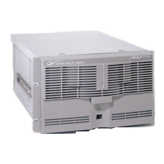
Product description Product description The Grass Valley Profile XP Media Platform provides a high bandwidth platform for the storage and manipulation of video and audio in professional applications including spot insertion, program delay, store and forward, and multi-channel replay. 0625-2... -
Page 16: Standard Accessories
Preface Standard accessories The Profile XP Media Platform is shipped with the following standard accessories: • Manuals Include: - Installation Guide - Profile XP System Guide - Profile XP User Guide - Profile XP Service Manual - Profile XP Release Notes •... -
Page 17: Profile Xp Media Platform Features
Profile XP Media Platform features Profile XP Media Platform features Features common to all media platforms • 16 (8 AES Pairs)/ 32 (16 AES pairs) channel audio - AES/EBU, embedded or analog uncompressed audio, Dolby E and AC-3 compressed audio •... -
Page 18: Pvs1000 Features
Preface PVS1000 features • Up to 8 standard definition (SD) channels of broadcast-quality video PVS1000 Series channel configurations by model Model Number of MPEG Number of MPEG Channel Number Encoder Boards Decoder Boards Configuration PVS1022 2 in/2 out PVS1024 2 in/ 4 out PVS1026 2 in/6 out PVS1042... -
Page 19: Pvs1100 Features
Profile XP Media Platform features PVS1100 features • Up to 8 standard definition (SD) channels of broadcast-quality video PVS1100 Series channel configurations by model Model Number of video Channel Number codecs Configuration PVS1102 2 play/record PVS1104 4 play/record PVS1106 6 play/record PVS1148 4 play/record plus 4 play... -
Page 20: Pvs2000 Features
Preface PVS2000 features • Up to 4 high definition (HD) channels of broadcast-quality video PVS2000 Series channel configurations by model Model Number of MPEG Number of MPEG Channel Number Encoder Boards Decoder Boards Configuration PVS2012 1 in/2 out PVS2013 1 in/ 3 out PVS2004 0 in/4 out PVS2022... -
Page 21: Pvs3000 Features
Profile XP Media Platform features PVS3000 features • Up to 7 channels of broadcast-quality video • Standard and high definition channels can record and play concurrently PVS 3000 Series channel configurations by model Model Number of HD Number of HD Number of SD Channel Number... -
Page 22: Pvs3500 Features
Preface PVS3500 features • Up to 7 channels of broadcast-quality video. • HD decoders can play MPEG-2 4:2:0 SD and HD clips through either an SD or an HD SDI output, down- or up-converted as required. PVS 3500 Series channel configurations by model Model Number of HD Number of HD... -
Page 23: Front Panel Controls And Indicators
Front panel controls and indicators Front panel controls and indicators The Profile XP Media Platform front panel shown here includes the following controls and indicators: - indicates the standby switch is in the on position and that Standby/On LED secondary voltages are present in the chassis. - provides system On/Off control. - Page 24 Preface The storage devices in the standard system include: - contains Windows NT operating system and Profile XP software System Drive and applications. - for installing operating system and Profile XP system 1.44MB Floppy Disk Drive software upgrades. - for installing operating system and Profile XP system software CD-ROM Drive upgrades.
- Page 25 Front panel controls and indicators The storage devices in the system with the redundant system disk option include: - contains Windows NT operating system and Profile XP Primary System Drive software and applications. - mirrors primary system disk and provides automatic fail-over Mirror System Disk in the event primary system disk fails.
-
Page 26: Profile Xp System Overview
Preface Profile XP system overview The Profile XP Media Platform system is an extension to a standard PCI bus based Windows NT Computer. This standard computer base is enhanced to add functionality and performance necessary to deliver an industrial grade, broadcast quality, disk-based media platform. -
Page 27: Real Time Subsystem
Profile XP system overview Real Time subsystem The Real Time Subsystem contains a real time processor and peripheral devices and runs the VXWorks operating system.The Real Time Subsystem manages all the hardware involved in controlling the flow of video, audio, and timecode in and out of the system. - Page 28 Preface Profile XP Service Manual 23 July 2004...
-
Page 29: Chapter 1 Characterizing The Problem
Chapter Characterizing the problem This is your first step in diagnosing the problem you are having with your Profile XP Media Platform. The information presented here and the questions asked will enable you to: • Determine the nature of the problem •... -
Page 30: What Has Changed
What attempts have you made to remedy the problem? Keep track of efforts you make to remedy your problem. In the event that you need to contact Grass Valley Support, this information can greatly assist the person working with you to isolate and correct the problem. -
Page 31: Diagnostic Tools
Diagnostic tools Diagnostic tools Several diagnostic tools are available to you for determining the nature and source of a problem. They are listed here with brief explanations of their uses, and they are discussed in more detail in Appendix A, Diagnostic Tools. Monitors the state of the Profile XP media platform, and alerts you to NetCentral —... - Page 32 Chapter 1 Characterizing the problem Profile XP Service Manual 23 July 2004...
-
Page 33: Chapter 2 Troubleshooting Windows Nt Boot Problems
Chapter Troubleshooting Windows NT boot problems This chapter deals with problems that occur between setting the switch to “on” and the appearance of the desktop on the monitor screen. During this period, the power-on self-test runs and Windows NT boots. Pre-boot problems The pre-boot sequence of events occurs when you first turn on the computer before Windows NT loads and begins to run. -
Page 34: Booting Windows Nt
Chapter 2 Troubleshooting Windows NT boot problems These are messages you might see reported by NetCentral at a remote monitoring station that relate to system startup for a Profile XP system. No entry in the Possible Cause column means that the cause is implicit in the problem statement, that knowing the cause is unimportant to the solution, or in the case of status messages, there is no cause. -
Page 35: Windows Nt Boot Problems
Windows NT boot problems LastKnownGood is loaded in when the user presses the space bar at the prompt before Windows NT begins to load. It is important to remember that when you invoke LastKnownGood, any system configuration changes made since the last successful start up are discarded. And once you successfully log on, the configuration used becomes LastKnownGood Windows NT boot problems Possible problems that occur during the Windows NT boot sequence are listed in the... -
Page 36: Using The Emergency Repair Process
Chapter 2 Troubleshooting Windows NT boot problems Using the emergency repair process The emergency repair data located in c:\winnt\repair and on the Emergency Repair Disk (ERD) is used to restore a Windows NT workstation back to the state of the last repair update. -
Page 37: Rebuilding The System Drive
Rebuilding the system drive 12.Insert the ERD when prompted. If you do not have an ERD, the repair process uses the repair data it finds under c:\winnt\system32\repair. 13.Confirm that you want your hard disk(s) examined for corruption by pressing Enter 14.The registry repair choices appear if you left “inspect registry files”... -
Page 38: Re-Installing And Configuring Drivers
Chapter 2 Troubleshooting Windows NT boot problems Re-installing and configuring drivers In the event that the display, Ethernet, or RS-422 drivers are corrupted or the settings lost, here is the information you need for re-installing the drivers and making settings that return the Profile XP media platform to its factory default conditions. -
Page 39: Chapter 3 Troubleshooting Video Problems
Chapter Troubleshooting video problems If your video problem is a result of equipment failure, your first indication might be a message in the NetCentral system. The tables of NetCentral messages list the Warning and Alarm messages you might see, with some possible causes and solutions. -
Page 40: Sdti Problems
Chapter 3 Troubleshooting video problems SDTI problems Problem Possible Causes Corrective Action The SDTI board in slot J-N This could be due to a Restart the Profile XP system, failed to initialize. communication failure between and run Profile diagnostics. the SDTI board realtime and I/O processors, or a hardware fault. -
Page 41: Video Playback (Decode) Problems
Video playback (decode) problems Video playback (decode) problems Problem Possible Causes Corrective Action Decoder# X failed to initialize Defective board, or problem Do one or more of the following: on slot J-N. with internal software. Check • Restart the Profile XP system. -
Page 42: Video Record (Encoder) Problems
Chapter 3 Troubleshooting video problems Video record (encoder) problems Problem Possible Causes Corrective Action Encoder# %d failed to initialize Defective board, or problem Do one or more of the following: on slot J-N. with internal software. Check • Restart the Profile XP system. -
Page 43: Correcting Common Setup Problems
Correcting common setup problems Correcting common setup problems This troubleshooting aid provides corrective action for some common record/play problems. Search the table for the problem you are experiencing, then try the corrective action. Some problems have more than one corrective action. Problem Possible Causes Corrective Action... -
Page 44: Correcting Common Video Problems
Chapter 3 Troubleshooting video problems Correcting common video problems This troubleshooting aid provides corrective action for some common video problems. Search the table for the problem you are experiencing, then try the corrective action. Some problems have more than one corrective action. Problem Possible Causes Corrective Action... -
Page 45: Chapter 4 Troubleshooting Audio Problems
Chapter Troubleshooting audio problems If your audio problem is a result of equipment failure, your first indication might be a message in the NetCentral system. The tables of NetCentral messages list the Warning and Alarm messages you might see, with some possible causes and solutions. -
Page 46: Audio Problems Related To Audio Board
Chapter 4 Troubleshooting audio problems Audio problems related to Audio board Problem Possible Causes Corrective Action Internal memory problems in the The DSP's internal memory Do one or more of the following: Digital Signal Processor during buffers have overflowed during •... - Page 47 Audio problems related to Audio board Problem Possible Causes Corrective Action The Profile is unable to connect If the audio subsystem cannot to the PAC216 serial I/O interrupt recover from this error condition, through the Audio board in slot try these solutions: J-N.
-
Page 48: Correcting Common Audio Problems
Chapter 4 Troubleshooting audio problems Correcting common audio problems This troubleshooting aid provides corrective action for some common audio problems. Search the table for the problem you are experiencing, then try the corrective action. Some problems have more than one corrective action. Problem Possible Causes Corrective Action... - Page 49 Correcting common audio problems Problem Possible Causes Corrective Action Embedded audio: Wrong video output selected. Select the correct video output. No audio output. Refer to “Select audio output format” in the Profile XP System Guide. Embedded audio: Incorrect audio group or channel Verify which embedded audio No audio output.
- Page 50 Chapter 4 Troubleshooting audio problems Profile XP Service Manual 23 July 2004...
- Page 51 Chapter Troubleshooting timecode problems If your timecode problem is a result of equipment failure, your first indication might be a message in the NetCentral system. The tables of NetCentral messages list the Warning and Alarm messages you might see, with some possible causes and solutions.
-
Page 52: Chapter 5 Troubleshooting Timecode Problems
Chapter 5 Troubleshooting timecode problems Checking NetCentral messages This table of NetCentral messages lists the message issued by the NetCentral system in response to timecode problems. Problem Possible Causes Corrective Action The Profile has detected Bad signal on video input. •... - Page 53 Correcting common timecode problems Problem Possible Causes Corrective Action VITC: There may be two sets of VITC Erase the VITC signal on the Incorrect VITC timecode on the on the video output and the video output (refer to “Erasing video output. external reader is reading the video input VBI information”...
- Page 54 Chapter 5 Troubleshooting timecode problems Profile XP Service Manual 23 July 2004...
- Page 55 Chapter Troubleshooting storage system problems The storage system troubleshooting described in this chapter covers local storage systems in which the RAID systems are connected directly to the media platform. If the media platform is part of an Open SAN, look for additional troubleshooting information in the Open SAN Instruction Manual.
-
Page 56: Chapter 6 Troubleshooting Storage System Problems
Chapter 6 Troubleshooting storage system problems Checking NetCentral messages – PFC500 These are NetCentral Warning and Alarm messages for PFC 500 Series Fibre Channel RAID Chassis. For PFR Series related monitoring, refer to “Monitoring PFR 500/600 Series storage with NetCentral” on page 62. and “Monitoring PFR 700 Series storage with NetCentral”... - Page 57 Checking NetCentral messages – PFC500 RAID storage messages Possible cause Corrective action The storage system is at Delete any unused media files. maximum capacity and is unable to store additional media. The system has reported sufficient storage capacity and is able to store additional media.
- Page 58 Chapter 6 Troubleshooting storage system problems RAID storage messages Possible cause Corrective action Fan module on RAID chassis Y Check whether the fan module is associated with controller X was inserted correctly into the removed or has shutdown. The chassis or replace the Fan controller(s) will power down module.
- Page 59 Checking NetCentral messages – PFC500 RAID storage messages Possible cause Corrective action RAID controller X that was Reboot the RAID system, then operating in non-mirrored the Profile. In Open SANs, caching mode has detected a consult reboot procedures in the non-recoverable memory fault Open SAN Instruction Manual, in the cache memory area.
- Page 60 Chapter 6 Troubleshooting storage system problems RAID storage messages Possible cause Corrective action Compression bitrate is set to a Restart the Profile, recheck for higher rate than the RAID messages, then run Profile system is able to process causing system diagnostics if needed. a storage bandwidth overflow.
-
Page 61: Locating A Drive Or A Chassis
Locating a drive or a chassis RAID storage messages Possible cause Corrective action The link control module in Restart the RAID system and the chassis Y associated with RAID Profile if using local storage. In controller X has failed. Open SANs, consult the Open SAN Instruction Manual, or contact Support. -
Page 62: Monitoring Pfr 500/600 Series Storage With Netcentral
Chapter 6 Troubleshooting storage system problems Monitoring PFR 500/600 Series storage with NetCentral This section includes the following: • “How to set up PFR 500/600 Series NetCentral monitoring” • “Using the PFR 500/600 Series device provider interface” How to set up PFR 500/600 Series NetCentral monitoring For PFR 500/600 Series RAID devices, the SNMP agent required for NetCentral monitoring runs on the RAID Controller module. - Page 63 Using the PFR 500/600 Series device provider interface 2. Select a subsystem for the RAID Controller to open the device provider interface and check sub-system status. 3. You can browse each RAID chassis subsystem in the same way. Alarm and Warning messages are also displayed in the NetCentral interface.
-
Page 64: Monitoring Pfr 700 Series Storage With Netcentral
Chapter 6 Troubleshooting storage system problems Monitoring PFR 700 Series storage with NetCentral For PFR 700 Series RAID devices, the SNMP agent required for NetCentral monitoring runs on the LAN card. The LAN card is a component in the PFR 700 RAID chassis. -
Page 65: Correcting Common Storage System Problems
Correcting common storage system problems Correcting common storage system problems This troubleshooting aid provides corrective action for some common storage system problems. Search the table for the problem you are experiencing, then try the corrective action. Some problems have more than one corrective action. Problem Possible Causes Corrective Action... - Page 66 Chapter 6 Troubleshooting storage system problems Profile XP Service Manual 23 July 2004...
-
Page 67: Chapter 7 Troubleshooting Video Network Problems
Chapter Troubleshooting video network problems If your video network problem is a result of equipment failure, your first indication might be a message in the NetCentral system. Look through the table in “Checking NetCentral messages” for the Warning or Alarm message you might see, and the suggested corrective action. -
Page 68: Correcting Common Fibre Channel Video Network Problems
Chapter 7 Troubleshooting video network problems Correcting common Fibre Channel video network problems This troubleshooting aid provides corrective action for some common Fibre Channel video network problems. Search the table for the problem you are experiencing, then try the corrective action. Some problems have more than one corrective action. The System Guide referred to in the tables in this chapter is the Profile XP System Guide. -
Page 69: Testing The Fibre Channel Video Network
Testing the Fibre Channel Video network Testing the Fibre Channel Video network Use this procedure to test your Fibre Channel video network setup. Testing the Ethernet name resolution and connectivity The Fibre Channel video network relies on Ethernet connectivity and name resolution.This procedure uses the ping command which requests a response from the named Profile XP system. -
Page 70: Testing Fibre Channel Name Resolution And Connectivity
Chapter 7 Troubleshooting video network problems NOTE: You may want to re-boot to ensure that any changes have taken effect. If, however, the ping command returns: Pinging 192.168.99.100 with 32 bytes of data: Request timed out. Request timed out. Request timed out. Request timed out. - Page 71 Testing the Fibre Channel Video network 3. In the Ping Window, select the option. Ping the Interface 4. Type fc0 in the text box, then click . Make sure to enter a zero not an O. All Ping Profile systems connected to Fibre Channel are asked to respond. 5.
-
Page 72: Correcting Common Ethernet Video Network Problems
Chapter 7 Troubleshooting video network problems Correcting common Ethernet video network problems This troubleshooting aid provides corrective action for some common Ethernet video network problems. Search the table for the problem you are experiencing, then try the corrective action. Some problems have more than one corrective action. Problem Possible Causes Corrective Action... -
Page 73: Testing The Ethernet Video Network
Testing the Ethernet Video network Testing the Ethernet Video network Use this procedure to test your Ethernet video network setup. Testing the Windows NT Ethernet name resolution and connectivity The video Ethernet video network relies on Windows NT Ethernet connectivity and name resolution.This procedure uses the ping command which requests a response from the named Profile XP system. -
Page 74: Testing Video Ethernet Name Resolution And Connectivity
Chapter 7 Troubleshooting video network problems If, however, the ping command returns: Pinging 192.168.99.100 with 32 bytes of data: Request timed out. Request timed out. Request timed out. Request timed out. One or both of the Profile XP systems appears to have a network connectivity problem. - Page 75 Testing the Ethernet Video network 3. In the Ping Window, select the option. Ping the Interface 4. Type le0 in the text box, then click . Make sure to enter a zero not an O. All Ping Profile systems are asked to respond. 5.
- Page 76 Chapter 7 Troubleshooting video network problems Profile XP Service Manual 23 July 2004...
-
Page 77: Chapter 8 Troubleshooting Miscellaneous System Problems
Chapter Troubleshooting miscellaneous system problems This chapter covers problems and NetCentral messages from a variety of subsystems in the Profile XP media platform including: • Problems related to the Applications Subsystem I/O, including tables for Ethernet problems and common problems associated with using Configuration Manager •... -
Page 78: Correcting Common Ethernet Network Problems
Chapter 8 Troubleshooting miscellaneous system problems Symptom Possible Causes Solution No display Component failure in Replace Applications Processor Applications Processor board board. Monitor or cable failure Replace cable or monitor as necessary. Correcting common Ethernet network problems This troubleshooting aid provides corrective action for some common Ethernet network problems. -
Page 79: Correcting Common Problems Using Configuration Manager
Correcting common problems using Configuration Manager Correcting common problems using Configuration Manager This troubleshooting aid provides corrective action for some common problems when using Configuration Manager. Search the table for the problem you are experiencing, then try the corrective action. Some problems have more than one corrective action. Problem Possible Causes Corrective Action... -
Page 80: Checking Real Time Processor Board Netcentral Messages
Chapter 8 Troubleshooting miscellaneous system problems Checking Real Time Processor board NetCentral messages These are the NetCentral Warning and Alarm messages you might see: Symptom Possible Causes Solution The Profile is not in sync with • Signal not present from source Do one or more of the following: the external reference signal. -
Page 81: Chapter 9 Troubleshooting Channel Control Problems
Chapter Troubleshooting channel control problems Correcting common channel control problems This troubleshooting aid provides corrective action for some common control problems. Search the table for the problem you are experiencing, then try the corrective action. Some problems can have more than one corrective action. The System Guide referred to in this table is the Profile XP System Guide. - Page 82 Chapter 9 Troubleshooting channel control problems Profile XP Service Manual 23 July 2004...
-
Page 83: Chapter 10 Routine Maintenance
Profile XP or PAC216. Additional air filters Additional air filters can be ordered directly from Grass Valley. See the Replaceable Parts Lists in Chapter 11 for the part numbers. Removing and replacing the Profile XP filters Removal of the air filters for cleaning or replacement requires removal of the front panel, but does not require shutting down the Profile XP. - Page 84 Chapter 10 Routine maintenance Reach further behind front panel and pull until top fasteners unsnap. Gently pull front panel until bottom fasteners unsnap. Turn over front panel Alignment and remove filters Posts (6) Attachment tabs (6 each) 0625-1 Removing the Profile XP Media Platform Front Panel and Air Filters Profile XP Service Manual 23 July 2004...
-
Page 85: Removing And Replacing The Pac216 Filter
Removing and replacing the PAC216 filter Removing and replacing the PAC216 filter Removal of the air filter for cleaning or replacement does not require removal of the PAC216 from the rack or the use of any tools. To remove the PAC216 air filter: 1. -
Page 86: Cleaning And Inspecting The Chassis
Chapter 10 Routine maintenance Cleaning and inspecting the chassis Any schedule established for cleaning and visually inspecting the equipment should be based on the environment in which it is operated and the amount it is used. Under average conditions, cleaning and visual inspection should be scheduled every 2000 hours of operation. -
Page 87: Updating The Emergency Repair Data
Updating the emergency repair data Updating the emergency repair data The emergency repair data located in c:\winnt\repair and on the Emergency Repair Disk (ERD) is used to restore a Windows NT workstation back to the state of the last repair update. It is used to search for missing or corrupt Windows NT files and to restore the registry files, including SAM database, security information, disk configuration, software registry entries, and other information. - Page 88 Chapter 10 Routine maintenance Profile XP Service Manual 23 July 2004...
-
Page 89: Chapter 11 Parts Removal And Replacement
Chapter Parts removal and replacement The pictures in this chapter show how to disassemble the Profile XP Media Platform. Re-assembly is the reverse. A list of field-replaceable parts is found at the end of the chapter. NOTE: Do not discard any hardware unless specifically instructed to do so. WARNING: To avoid serious injury from high currents, ensure that the power cord is disconnected prior to removing or replacing any internal parts. -
Page 90: Removing The Fan Unit
Chapter 11 Parts removal and replacement Removing the fan unit When removing the fan unit, hook forefingers in the holes on the fan unit and pull while pressing the thumbs against the edge of the chassis. Pry with thumbs against chassis to unseat fan unit. -
Page 91: Removing The System Disk, Floppy Disk, Or Cd-Rom Drive
Profile XP System Drive Rebuild CD-ROM that you received with your Profile XP system or from Grass Valley Support. If you are restoring a corrupt system disk on which the information is unusable, you must perform the following procedure to restore the system to operation. - Page 92 Chapter 11 Parts removal and replacement 3. Adjust the order of the boot devices as necessary so that they appear as follows: Removable Devices (floppy drive) CD-ROM Hard Drive 4. Place the Profile XP System Drive Rebuild CD-ROM in the CD-ROM drive. 5.
- Page 93 External Parts Removal a. Use Windows NT Explorer to run Disk 1\Setup.exe. b. Follow the directions, being sure to select “Yes, I want to restart…” in the Setup Complete window. 18. Log on as administrator. 19. Start the Configuration Manager. 20.
-
Page 94: Removing The Power Supplies
Chapter 11 Parts removal and replacement Removing the power supplies When removing a power supply, unplug its ac power cable before removing the power supply from the cabinet. Loosen retaining screw(s) 0625-26 Profile XP Service Manual 23 July 2004... -
Page 95: Internal Parts Removal
Internal parts removal Internal parts removal The illustrations that follow show how to remove all the internal parts of the Profile XP Media Platform beginning with removing the top cover and finishing with removing the motherboard from the bottom of the cabinet. The last illustration shows the cable connections on the front of the Motherboard to aid in reassembly. -
Page 96: Removing And Installing Plug-In Circuit Boards
Chapter 11 Parts removal and replacement Removing and installing plug-in circuit boards Board Installation Details Remove screws NOTE: Holding the lever up while pushing down on the board can jam it against the bulkhead, making board extraction extremely difficult. To install a board, follow these steps (refer to the installation detail in the illustration): 1. -
Page 97: Removing The Processor Board
NOTE: If you need to replace the processor board, check the part number on the board and order a replacement board with that part number. Refer to “Field-replaceable parts” on page 119. for the Grass Valley part numbers. 0625-14 Removing the air chamber Lift up to unhook, then forward. -
Page 98: Removing The Standby/On Switch And Fault Led
Chapter 11 Parts removal and replacement Removing the standby/on switch and fault LED Fault LED Standby/On Switch Disconnect cabling from Mother Board Remove Standby/On Switch and Fault LED 0625-15 Profile XP Service Manual 23 July 2004... -
Page 99: Removing The Power Distribution Board
Internal parts removal Removing the power distribution board Loosen Power Supply(s) Pry up on metal approx. 1/4" tab to unseat board. Carefully angle board and remove from chassis. Loosen CDROM drive approx. 1/4" 0625-9 23 July 2004 Profile XP Service Manual... -
Page 100: Removing The Bulkhead
Chapter 11 Parts removal and replacement Removing the bulkhead 0625-11 Profile XP Service Manual 23 July 2004... -
Page 101: Replacing The Motherboard
Replacing the motherboard Replacing the motherboard To replace the motherboard, you must first remove all connected components such as circuit boards and cables. When installing the replacement board, you must install Profile System Software on the new board prior to installing the other circuit boards in the system. -
Page 102: Installing The Motherboard
Chapter 11 Parts removal and replacement Installing the motherboard To install the motherboard: 1. Carefully lower the motherboard into position and fasten it to the chassis with the removed screws. 2. Attach all disconnected cables as shown in the following illustration. IDE Drive Power Distribution... - Page 103 Replacing the motherboard 5. Power on the system, log on as administrator, and install the desired version of Profile System Software. NOTE: Ignore messages about Services that did not start and other messages caused by the absence of circuit boards. 6.
-
Page 104: Replacing Parts In A System With The Redundancy Option
Chapter 11 Parts removal and replacement Replacing parts in a system with the redundancy option When removing or installing the DupliDisk controller, the primary or mirror system disk drives, or the Superdrive 3.5" diskette drive, refer to the illustrations that follow as you perform the steps in the procedure. -
Page 105: Interpreting The Duplidisk Iii Control Panel Leds
Replacing parts in a system with the redundancy option Interpreting the DupliDisk III control panel LEDs The following describes how to interpret the control panel LEDs. The Primary and Mirror LEDs display the status of the disk hardware on the Primary and Mirror channels. -
Page 106: Replacing A Redundant System Disk Drive: Duplidisk Iii Controller
Chapter 11 Parts removal and replacement Replacing a redundant system disk drive: DupliDisk III Controller If one of the system disk drives fails, the buzzer in the DupliDisk controller sounds, indicating the drive has failed. The failed drive LED flashes RED, and the Master LED turns RED. - Page 107 Replacing parts in a system with the redundancy option DupliDisk II Adapter Setup Utility (Bay) Initialization Status Primary Channel Master: not present Slave: not present Mirror Channel Master: Fujitsu MPE3102AT hd(16) cyl(19856) spt(0) cap(63Mb) Slave: not present Initialization Information Primary Master: ..... MARKED AS BAD Mirror Master: Fujitsu MPE3102AT..Initialized Master Drives are NOT in MIRROR mode.
-
Page 108: Creating A Bootable Duplidisk Utilities Diskette
Chapter 11 Parts removal and replacement 19. When the Master Drive Configuration box appears, perform one of the following steps: - If the PRIMARY drive was replaced, highlight Rebuild drive on Primary Channel, then press Enter - If the MIRROR drive was replaced, highlight Rebuild drive on the Mirror Channel, then press Enter The Copy Drive dialog box appears displaying drive copy status and estimated... -
Page 109: Interpreting The Duplidisk Ii Control Panel Leds
Replacing parts in a system with the redundancy option Interpreting the DupliDisk II control panel LEDs The following describes how to interpret the control panel LEDs. The Primary and Mirror LEDs display the status of the disk hardware on the Primary and Mirror channels. -
Page 110: Replacing A Redundant System Disk Drive: Duplidisk Ii Controller
Chapter 11 Parts removal and replacement Replacing a redundant system disk drive: DupliDisk II Controller If one of the system disk drives fail, the buzzer in the DupliDisk II controller sounds, indicating the drive has failed. The failed drive LED flashes RED, and the Master LED turns RED. - Page 111 Replacing parts in a system with the redundancy option DupliDisk II Adapter Setup Utility (Bay) Initialization Status Primary Channel Master: not present Slave: not present Mirror Channel Master: Fujitsu MPE3102AT hd(16) cyl(19856) spt(0) cap(63Mb) Slave: not present Initialization Information Primary Master: ..... MARKED AS BAD Mirror Master: Fujitsu MPE3102AT..Initialized Master Drives are NOT in MIRROR mode.
- Page 112 Chapter 11 Parts removal and replacement 19. When the Master Drive Configuration box appears, perform one of the following steps: - If the PRIMARY drive was replaced, highlight Rebuild drive on Primary Channel, then press Enter - If the MIRROR drive was replaced, highlight Rebuild drive on the Mirror Channel, then press Enter The Copy Drive dialog box appears displaying drive copy status and estimated...
-
Page 113: Replacing A Redundant System Disk Drive: Duplidisk Controller
Replacing parts in a system with the redundancy option Replacing a redundant system disk drive: DupliDisk Controller If one of the system disk drives fails, the buzzer in the DupliDisk controller sounds once indicating the drive has failed; both the drive and status LEDs turn red, and the NetCentral system generates a Warning message. - Page 114 Chapter 11 Parts removal and replacement Status LED is Red. On the screen, percentage complete display is periodically updated, and a rotating bar character indicates that the operation is progressing. 17. When the following message appears in the Status dialog box, remove the DupliDisk ACP Mirroring Utility diskette from the disk drive, then press Enter “Drives are identical!!!!!
-
Page 115: Restoring A Corrupt System Drive
Replacing parts in a system with the redundancy option Restoring a corrupt system drive Use the Profile XP System Drive Rebuild CD-ROM you received with your PVS1000 and the following procedure to restore a system disk drive where the information on the primary disk is unusable, which results in the mirror drive being unusable as well. - Page 116 Chapter 11 Parts removal and replacement c. In the Network window, change the computer name and network addresses as needed. Check with your system administrator for the correct information to enter. For more information about setting up the network, refer to the Profile XP System Guide.
- Page 117 Replacing parts in a system with the redundancy option Motherboard Drive Cable Dressing Primary Drive Cable IDE Drive Mirrored Drive Cable Floppy Drive (Power) Serial Port IDE Drive (Power) Fold primary drive cable first and dress both cables as shown To Primary Drive Fold these cables as shown.
-
Page 118: Replacing The Superdrive
Chapter 11 Parts removal and replacement Replacing the Superdrive To replace the Superdrive in the Profile XP chassis: 1. Shut down the Profile XP system and remove the front panel, fan unit, top cover, and air chamber from the Profile XP chassis to allow access to the cable connectors on the motherboard and the back of the drives installed in the bays. -
Page 119: Field-Replaceable Parts
Field-replaceable parts Field-replaceable parts The parts listed in this table are the parts that you can order from Grass Valley and replace on-site. Description Part Number Applications Processor Module (NLX) 039-0081-XX or 115-0002-XX Ethernet board 039-0087-XX RS422 board 116-0331-XX Fibre Channel Network board... - Page 120 Chapter 11 Parts removal and replacement Description Part Number Cable Assy., Standby/Power Switch 174-4042-XX Cable, RS422 to I/O Panel 174-4343-XX Cable, Real Time System board to I/O Panel 174-4344-XX Top Cover 200-4523-XX Front Bezel 333-4327-XX Air Filter, Door 378-0474-XX Air Filter, Bezel 378-0475-XX Front Panel Assy.
-
Page 121: Appendix A Diagnostic Tools
• Profile Log Tools—WinTail is a log viewer that allows you to view Profile system logs. Log Capture is a tool that captures the contents of the c:\profile\logs directory into a .zip file for transmission to Grass Valley Support. • Profile XP Diagnostics— A diagnostic suite that checks the functionality of the boards in the Profile XP Media Platform. -
Page 122: Using Netcentral Lite
Appendix A Diagnostic Tools Using NetCentral Lite This section documents version 2 of the NetCentral Lite product. Other versions of NetCentral Lite are similar. To view the specific documentation for your version of NetCentral, on the NetCentral main window click Help | Help Topics NetCentral Lite is the version of NetCentral supplied with every Profile XP media platform. -
Page 123: Viewing The System Tray Icon
Interpreting status indicators NetCentral Lite indicates these status levels throughout the interface, using the following icons, colors, animations, and actions: Normal Warning Alarm Dead or Off-line System tray icon Green color block Red color block Red color block Red color block Main window device view Main window sub-... -
Page 124: Viewing The Netcentral Lite Main Window
Appendix A Diagnostic Tools Viewing the NetCentral Lite main window This section documents NetCentral II Lite. For NetCentral III Lite click Help | Help to view similar documentation. Topics Similar to Windows Explorer, the information in the window is organized into different views which can be manipulated as shown here: Profile XP status is indicated within the different views as follows: This panel lists the Profile XP Media Platform being monitored by... -
Page 125: Responding To Messages
Viewing the NetCentral Lite main window Responding to messages NetCentral Lite notifies you immediately if your media platform reaches a status-level of alarm or warning by popping up the main window and sounding an audible beep. Other actions can be triggered as well, such as sending an e-mail message. -
Page 126: To Clear Informational Messages
Appendix A Diagnostic Tools To clear informational messages Since normal informational messages persist in the NetCentral II system window as long as the status condition remains normal, you may accumulate obsolete messages from problems resolved long ago. If want to clear informational messages, click . -
Page 127: Viewing Subsystem Properties
Viewing subsystem properties Viewing subsystem properties To display the properties for a subsystem, click on the icon displayed in the subsystem view. You can also display subsystem properties by clicking on the button in the Properties tool bar or by choosing . -
Page 128: To View Thermal Properties
Appendix A Diagnostic Tools To view Thermal properties 1. Select the tab in the Properties window. Thermal 2. Select Fahrenheit or Centigrade units for temperature reporting. The Thermal properties panel shows you the current operating temperature of the media platform. The green area on the thermometer shows the safe range of operating temperatures, the yellow area shows the temperature range in which NetCentral Lite sends a Warning message, and the red area shows the temperature range that generates an Alarm message. - Page 129 Viewing subsystem properties 23 July 2004 Profile XP Service Manual...
-
Page 130: To Set Storage Time Remaining Estimate Perimeters
Appendix A Diagnostic Tools To set storage time remaining estimate perimeters: 1. Select the tab in the Properties window. Storage 2. Click Settings 3. The storage time remaining estimate is based on the values that you enter in the Disk Capacity setting as shown below. Select the compression method and data rate being used by the media platform to allow NetCentral to accurately estimate the remaining storage capacity in the RAID storage subsystem. -
Page 131: To View Timing Properties
Viewing subsystem properties To view Timing properties • Select the tab in the Properties window. Timing This panel reports the video standard in use (NTSC or PAL), and indicates with green “lights” when the system is locked to the reference, and when VITC and LTC timecodes are present. -
Page 132: To View Video And Audio Properties
Appendix A Diagnostic Tools To view Video and Audio properties • Select the tab in the Properties window Video/Audio Video properties are displayed in the upper portion of the panel, and Audio properties in the lower portion. The green lights indicate which signals are present. Profile XP Service Manual 23 July 2004... -
Page 133: To View Board Status
Viewing subsystem properties To view Board Status • Select the tab in the Properties window. Board Status This panel lists the boards that are installed in the Profile XP media platform, the slot in which each is installed, version of the board installed, and its current status. 23 July 2004 Profile XP Service Manual... -
Page 134: To View Network Properties
Appendix A Diagnostic Tools To view network properties • Select the tab in the Properties window. Network This panel lists the fibre channel network properties for the Profile XP Media Platform. Use the Configuration Manager program to set or change these properties. Information for doing this can be found in the Profile XP System Guide. -
Page 135: Configuring Messages
Configuring messages Configuring messages Monitoring station initiated messages are controlled from within the NetCentral software. An example of this type of message is when the Profile XP system responds to the NetCentral software’s heartbeat polling. You can configure heartbeat polling as explained in the next section. - Page 136 Appendix A Diagnostic Tools To set parameters for heartbeat polling 1. Choose . The System Settings dialog box appears. Configure | System Settings 2. As indicated by the interface text, adjust the sliders to set the time allowance NetCentral Lite exercises before it declares a system off-line. Set the “Interval between heartbeat checks”...
-
Page 137: Ignoring Messages
Configuring messages Ignoring messages This section documents NetCentral II Lite. For NetCentral III Lite click Help | Help to view similar documentation. Topics If you find that some messages are not necessary, you can have NetCentral Lite selectively ignore messages. For example, if a project requires frequent changes in the timing parameters on your Profile XP Media Platform, you might want to have NetCentral Lite ignore the “System timing out of sync”... -
Page 138: Configuring Actions And Notifications
Appendix A Diagnostic Tools 7. When you are satisfied with your settings, click the button to put the settings into effect and close the dialog box. Configuring actions and notifications You can configure NetCentral Lite to trigger one or more actions whenever it receives an alarm or warning message. - Page 139 Configuring actions and notifications 3. Click the button. The properties dialog box appears for the type of Add to List action you have selected. Configure the properties and test as desired. Read the explanation later in this section for information about configuring properties and testing for the type of action you have selected.
-
Page 140: Controlling The Front Panel Led
Appendix A Diagnostic Tools Controlling the front panel LED You can configure the LED on the front panel of the Profile XP Media Platform to flash whenever an alarm or warning condition occurs, as explained in this section. Configuring the Flash LED action 1. - Page 141 Configuring actions and notifications 5. If your environment uses unique SNMP community names, enter the appropriate SNMP community name. Otherwise, accept “public” as the default name. 6. Select the option that controls the LED as desired. In most cases you will select “On”...
-
Page 142: Sending E-Mail And Pager Notifications
Appendix A Diagnostic Tools Sending e-mail and pager notifications This section documents NetCentral II Lite. For NetCentral III Lite click Help | Help to view similar documentation. Topics The Send Mail action is the only e-mail action available in NetCentral Lite. This action sends the full text of the alarm or warning message as e-mail to the address that you specify. -
Page 143: Playing A Beep
Configuring actions and notifications Playing a beep This section documents NetCentral II Lite. For NetCentral III Lite click Help | Help to view similar documentation. Topics When you add the Beep action, NetCentral Lite automatically plays a beep on the monitoring station PC. -
Page 144: Running A Program
Appendix A Diagnostic Tools Running a program This section documents NetCentral II Lite. For NetCentral III Lite click Help | Help to view similar documentation. Topics When you add the Run Program action, NetCentral Lite automatically executes a program of your choice. In order to configure properties and add this action, you will need make the following preparations: •... -
Page 145: Triggering Profile Xp Gpi Outputs
Configuring actions and notifications Triggering Profile XP GPI outputs Two outputs, GPI-OUT 7 and GPI-OUT 8, are available for use by NetCentral Lite. If you use only one GPI output, use GPI-OUT 8. By triggering a GPI output, you can activate an external alarm or indicating device when an Alarm or Warning condition occurs. -
Page 146: Making Settings For A Profile Xp System
Appendix A Diagnostic Tools 7. Click when you are finished configuring the GPI outputs. 8. Restart the system. You can test the GPI outputs by using the button. Test If you re-install Profile System Software, you must reconfigure the GPI outputs. If you allocate GPI outputs 7 and 8 for use by some other application, you must restart the Profile System. -
Page 147: Profile Log Tools
The Profile Log Capture Tool is used to capture the contents of the c:\profile\logs directory and package them in .zip format to be sent to Grass Valley Support. To start the Log Capture tool, double-click the Log Capture icon on the Windows NT desktop, choose and enter C:\profile\logstool.exe in the text entry field, or enter... - Page 148 Custom file size blocks (minimum 2). The single file and custom file size selections allow you to choose the file size that is most convenient for you to ftp or e-mail to Grass Valley Support. Profile XP Service Manual 23 July 2004...
- Page 149 NOTE: Clicking OK does not send any files to Grass Valley Support, it merely ends the program. To send the files, you must copy them to floppy disk, or transmit them using ftp or e-mail.
- Page 150 Appendix A Diagnostic Tools Profile XP Service Manual 23 July 2004...
-
Page 151: Profile Xp Diagnostics
Profile XP diagnostics Profile XP diagnostics Profile XP diagnostics provide a means of testing the circuit boards installed in the Profile XP unit either individually or as a group. Before you start Profile XP diagnostics, you must disconnect all video and reference signal cables (Fibre Channel and external disk connections should remain connected). - Page 152 Appendix A Diagnostic Tools Profile XP Service Manual 23 July 2004...
-
Page 153: Windows Nt Diagnostic Tools
Windows NT diagnostic tools Windows NT diagnostic tools The Windows NT diagnostics and event viewer are found by clicking . The registry editor must be accessed from Start | Programs | Administrative Tools menu in the Windows NT diagnostics. File | Run Windows NT diagnostics This utility provides administrators with information on the operating system version, application-server hardware, memory, drivers, services, IRQs, network, and disk... -
Page 154: Event Types
Appendix A Diagnostic Tools The Security Log records events relating to system security, such as failed logons. The Application Log records events generated by applications, such as “log file too large.” Logs can be saved for analysis, and with proper access rights, logs on remote computers and be viewed over the network. -
Page 155: Role Of The Registry During Boot
Registry editor Root Key Name Description HKEY_USERS Contains all actively loaded user profiles, including HKEY_CURRENT_USER, which always refers to a child of HKEY_USERS, and the default profile. HKEY_CLASSES_ROOT Contains file association data and object linking and embedding data. (equivalent to the Registry in Windows for MS-DOS. NOTE: The “H”... - Page 156 Appendix A Diagnostic Tools Profile XP Service Manual 23 July 2004...
-
Page 157: Appendix B Theory Of Operation
Appendix Theory of operation This appendix is a high-level overview of the Profile XP media platform that provides a basic understanding of system operation to support module-level servicing. Architecture overview The Profile XP architecture is an extension to a standard PCI bus-based computer that uses the Window NT operating system. - Page 158 Appendix B Theory of operation Real Time Subsystem Media Storage Subsystem Fibre Channel Disk Interface Port A Port B 2In/2Out Video Compression Local or Shared Storage (up to 8 channels Crosspoint total) Examples MPEG-2 Encoder (2Ch SD) 4Out Applications Subsystem MPEG-2 Decoder SVGA...
- Page 159 Architecture overview Real Time Subsystem Media Storage Subsystem Not Available when NTSC/PAL Embedded Audio is used. Fibre Channel SD SDI Disk Interface HD out HD SDI Video HD in Port A Port B Compression " & " & MPEG-2 Encoder PFC 500 System HD SDI (RAID 3 Storage)
- Page 160 Appendix B Theory of operation Real Time Subsystem SDTI Media Storage 2In/2Out Subsystem Fibre Channel Disk Interface Video Port A Port B 2In/2Out Compression (up to 8 channels total) Local or Shared Storage Crosspoint Examples Video Processor Board 4Out Codec Applications Subsystem Codec SVGA...
-
Page 161: Applications Subsystem (Windows Nt System)
Applications subsystem (Windows NT system) Applications subsystem (Windows NT system) The applications subsystem executes and controls the standard user interface (GUI), system control I/O, system configuration, and the various applications that control the system from a functional level. The application subsystem consists of the applications processor, the user input and display devices, various applications system disk storage devices, and an 8-channel RS-422 interface. -
Page 162: Real Time Subsystem
Appendix B Theory of operation Real time subsystem The real time subsystem is responsible for the following functions in the Profile XP system: • manages the data flow to and from, and the real time control of, the encoders and decoders, the video, audio, and time code I/O, and the media storage subsystem. -
Page 163: Mpeg-2 Encoder And Decoder Boards (Pvs1000 Series)
MPEG-2 Encoder and Decoder boards (PVS1000 Series) MPEG-2 Encoder and Decoder boards (PVS1000 Series) The MPEG-2 Encoder board receives an uncompressed video stream of CCIR 601 video data from the video/audio crosspoint fabric and compresses (encodes) it into MPEG-2 format. The MPEG-2 video is then sent over the PCI bus to the media storage subsystem. -
Page 164: Serial Digital Interface (Sdi) Boards
Appendix B Theory of operation Serial Digital Interface (SDI) boards The SDI boards used in the Profile XP media platform provide either two input and two output ports, or four output ports. The SDI inputs receive serial component video conforming to SMPTE 259M. The input decoder synchronizes the incoming video to the Profile XP internal video timing and converts the serial stream into 10-bit component 4:2:2 video that is sent to the video/audio crosspoint fabric. -
Page 165: Audio Interface
Audio interface Audio interface The audio interface receives external analog or AES/EBU digital audio signals and converts them into the internal form used by the Audio board. The audio interface also receives data from the audio processor and converts it to the appropriate external audio signal. -
Page 166: Platform Resources
Appendix B Theory of operation Platform resources The platform resources provide the infrastructure necessary to operate, interconnect, and integrate all the application subsystem and real time subsystem components. The elements that make up the platform resources are found mostly (but not exclusively) on the Motherboard and include the following: •... -
Page 167: Index
Index Audio problems About this manual 13 common problems 48 Accessories, standard 16 NetCentral messages 45 actions adding 138 Beep 143 Beep action cancelling 125 configuring 143 configuring 138 turning off 125 Flash LED 140 Booting Windows NT 34 GPI outputs 145 Bulkhead, removing 100 modifying 139 preparation before adding 138... - Page 168 Index Controls and indicators 23 Error detection 30 Ethernet common problems 78 decoder Ethernet Interface 161 HD MPEG-2 163 Ethernet, testing the video network 73 MPEG-2 (SD) 163 Event viewer 153 devices Exterior Cleaning 86 parameters for threshold conditions on External parts removal 89 viewing General Properties 127 Diagnostic tools 31...
- Page 169 colors in system tray 123 ignoring 137 ignoring messages 137 in the NetCentral window 125 Indicators suggestions for corrective actions 124 DupliDisk controller 25 Monitoring system 30 front panel 23 Motherboard Indicators and controls 23 removing 101 informational messages MPEG-2 encoder and decoder 163 clearing 126 defined 122 injury precautions 5...
- Page 170 Index air filters 83 Redundancy option 104 bulkhead 100 Redundant system disk drive CD ROM drive 91 replacing 106, 110, 113 circuit boards 96 Redundant system drive 25 external 89 Registry editor 154 fan unit 90 Related documentation 14 floppy disk 91 Removal and Replacement front panel 89 Air Filters 83...
- Page 171 Standard accessories 16 Top cover, removing 95 status indicators 122 Trap Destination Address, setting 122 status levels defined 122 Troubleshooting stopping sounds 125 applications subsystem problems 77 Storage system (RAID) audio problems 45 common problems 65 channel control problems 81 NetCentral messages 56 storage system (RAID) problems 55 Subsystem...
- Page 172 Index Profile XP Service Manual 23 July 2004...
Need help?
Do you have a question about the Profile XP PVS1000 and is the answer not in the manual?
Questions and answers