Table of Contents
Advertisement
Quick Links
Advertisement
Table of Contents

Subscribe to Our Youtube Channel
Summary of Contents for Stewart Audio AV25-2-RS232
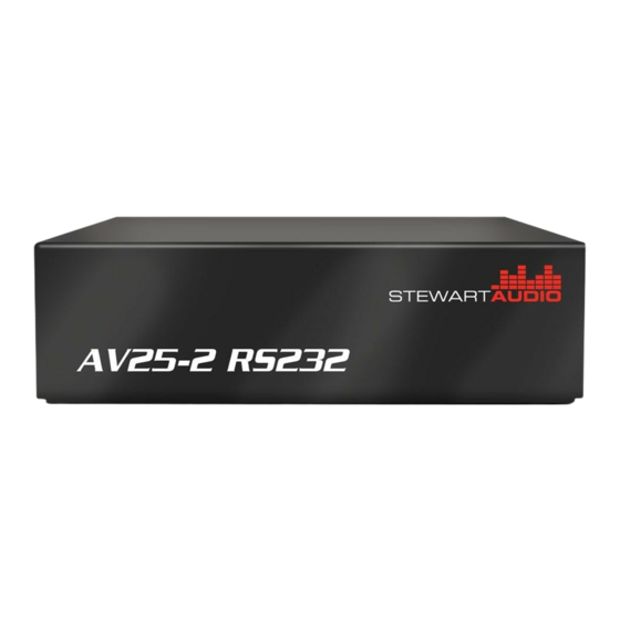
- Page 1 AV25-2-RS232 AV25-2 RS232 Owner’s Manual January 2012 www.stewartaudio.com...
-
Page 2: Important Safety Instructions
Airflow through the ventilation openings should be Before using your Stewart Audio Inc. Power Amplifier, please read this unobstructed. Owner’s Manual carefully to ensure optimum trouble-free perfor- mance. -
Page 3: Table Of Contents
2.4 Input Connections ······························································· 9 1.1 Features 2.5 Output Connections ·························································· 11 Your Stewart Audio AV Series amplifier is the result of years of 3 Operation ······················································································ 12 experience in the design and manufacture of quality amplifiers. As such 3.1 Operation Precautions ······················································· 12 it provides a combination of performance and operational benefits that 3.2 Controls, Indicators, and Connectors ································... -
Page 4: Setup
2.2.1 Pole-Mounting The AV Series of amplifiers is Stewart Audio’s first line of pole- mountable amplifiers. The AV25-2-RS232 has mount holes on both the top as well as the side of the unit which can be used with the AV-Pole bracket available from Stewart Audio. -
Page 5: Proper Cooling Considerations
When using a balanced input source and connector, you must ensure that the hot, cold, and ground pins of the connector are matched up to the +, -, and ground pins of the AV25-2-RS232’s Phoenix connector respectively. Diagrams have been provided for standard XLR and TRS 3.2in... -
Page 6: Output Connections
2.4.2 Unbalanced Connections 2.5 Output Connections Stewart Audio recommends using high-quality, heavy-gauge speaker When using an unbalanced input source and connector, a jumper must wire and connectors to send the output signal of your amplifier to the be added between the negative (-) terminals and the ground terminals. -
Page 7: Operation
Using equipment that is not capable of handling the output wattage may lead to permanent damage. PLENUM RATED NOTE: Stewart Audio will not be held responsible for LEVEL damage to your AV25-2-RS232 or connected equipment if the instructions in this manual are not followed. -
Page 8: Rs232 Control
All communication should 3.2.2 Controls be done at 9600 baud. All AV25-2-RS232 controls are located on the rear of the unit. There is 4.1 RS232 Connection no power switch so the AV25-2-RS232 will turn on whenever power is supplied to it. -
Page 9: Rs232 Commands
4.3 RS232 Commands 5 Troubleshooting Command Names and Description Hex Command Problem: Power indicator does not turn on. VOLUME_UP 0x02 0x76 0x75 0x03 Procedure: Check that the amplifier is plugged into a live outlet. After Increases the volume by 10% you have ensured that it is not a power issue, disconnect any speakers. -
Page 10: 6Technical Specifications
External In-Line 48DVC Cooling Convection-Cooling Controls Level LED Indicators Power, Signal Present & Clip Construction Aluminum Chassis Dimensions Height 1.25in (3.2cm) Width 4.35in (11.1cm) Depth 3.2in (8.1cm) Weight 0.37bs (0.16kg) Stewart Audio reserves the rate to change features and specifications without notice. -
Page 11: Warranty Information
3-year limited warranty on parts and labor from the data of purchase. In order to be eligible for warranty repairs, If Stewart Audio is unable to contact the sender in 14 days, the mer- the amplifiers and accessories must have been purchased through an chandise will be considered scrap and may be disposed of. - Page 12 7.2.3 Packaging Instructions (cont.) 1. Please write the RA number on three sides of the box. Include the Stewart Audio RA number inside the box and a brief description of the problem. 2. Do not ship any accessories (manuals, cords, hardware, etc.) with your unit.


Need help?
Do you have a question about the AV25-2-RS232 and is the answer not in the manual?
Questions and answers