
Related Manuals for Alto Contractor Diesel


Summary of Contents for Alto Contractor Diesel
- Page 1 CONTRACTOR DIESEL Repair Manual 2003-11-14...
- Page 2 ALTO Danmark A/S Industrikvarteret DK-9560 Hadsund Tel.: +45 7218 2100 www.alto-online.com Copyright © 2003 ALTO Danmark A/S...
- Page 3 Technical data Structure Function Trouble-shooting INDEX Service / Repair CONTRACTOR Diesel Petrol Test / Adjustment El. diagrams Spare parts proposal (Info & spare parts)
- Page 4 CONTRACTOR Diesel Motor data Diesel motor RUGGERINI MD 151, S Engine type 4 stroke two cylinder Max. output at 3600 rpm 13 HP / continuous 12.3 HP Max. torque st 2400 rpm 3.26 Kgm Fuel consumption Approx. 3 l/h Fuel tank capacity 4.1 l...
- Page 5 CONTRACTOR Diesel Pump data Heavy Duty Opening pressure 210 bar Pump pressure 180 bar / 2550 psi 205 Nozzle pressure 170 bar / 2410 psi 195 By-pass pressure 8 bar Water quantity at min./max. pressure 20/19 l/min. 17.5/16 l/min. Water quantity at steam 9 l/min.
- Page 6 CONTRACTOR Diesel Boiler data Heavy Duty Boiler effect 115 kW Water outlet temp. at max. water quantity (12°C) 95°C (205°F) Oil consumption at max. water quantity and temp. 12 l/h 10 l/h 10-12% 50-100 ppm Temp. fl ue gas at 20°C ambient temp.
- Page 7 CONTRACTOR Diesel Electrical parts A1 KEW-steering 24V AC 642009A A2 KEW-converter 12V DC / 24V AC 6420013 B1 Flow control After pump magnet oper. Reed-switch B2 Flow control Before boiler magn. oper. Reed-switch B4/B5 Temperature sensor PT500 B6 Flame sensor...
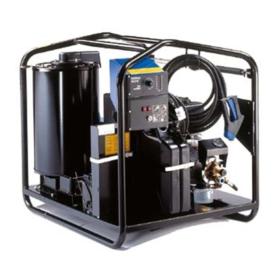
- Page 8 Setup Structure The Contractor is constructed on a combined pipe and plate frame, sur face coated with a strong po ly - ester. Each sing le item of the machine is placed in a way that an op ti mum weight di stri bu ti on is obtained taking service and operation into con si de ra ti on.
- Page 9 Setup Structure Pump front Manometer Water quantity regulation Water inlet Water outlet Flow switch B1 Pressure outlet Electromagnet Y2 Y3 (safety stop) Sludge glass Starter relay Starting motor Gearbox Diesel oil for pump Motor connection (- pinch) Oil pressure Rectifi er G3 switch B7 Blower Motor air fi...
- Page 10 Boiler Structure The boiler is the heat ge ne ra ting part of a hot water mac hi ne. It consists of a labyrinth-constructed tube coil, which encloses the combustion chamber. The tube coil is enclosed by a dou ble con tai ner with boilerjacket, bottom, and top in a sandwich con- struction, between which the combustion air is pressed into the combustion.
-
Page 11: Wobble Disc
Pump Structure The pump is a 4 cyl. axial pump model 03 with stan dard sealing system and steel pis tons, or model C3 with text ile seals and and ceramic pistons. The pump is driven by the mo tor through a gear, which reduces the number of re vo lu ti ons of the spindle from 3500 rpm to 1750 rpm. -
Page 12: Operating Diagram
Operating diagram Function When the Contractor is running, the fan draws in air and leads it through a channel with an air volume adjustment and into the bottom of the boiler, around and between the two jackets up to the air distributor. In this way the air is preheated, before it is mixed with the oil spray from the nozzle. - Page 13 Operating diagram Function The fl ow system is simp le with direct water inlet to the pump (water tank can be mounted), on which an adjusting screw permits infi nitely variable regulation of the water quantity. From the pump the water pas- ses two fl...
- Page 14 Operating diagram Function The controlling and safety system of the Contractor consists of the PC-board A1, the main task of which it is to secure ope ra ti on and safety of the boiler sy stem. The PC-board A2 is a con ver ter, the main tasks of which it is to convert 12 V DC to 24 V AC and to supply the ignition trans for mer with 2x12V AC.
- Page 15 EL.-control Function Plug for test box no. 6420100, see page 32. 8 7 6 5 4 3 2 1 Temperature range selector safe pump motor The A1 PC-board is supplied with 24V AC from the con ver ter PC-board A2, and it is controlling the oil injection (Y1) into the boiler with a 24V sig nal of X2, 4 and 5.
- Page 16 EL.-control Function Starting rev., 24VAC: 2500 rpm ±10% Declutching rev., 24VAC: 2300 rpm ±10% Temperature ran ge: 0-65°C Securing of tem pe ra tu re - ignition trans for mer: Interrupts at 90°C ±5°C Connections: +battery -battery ignition trans for mer double wire ignition trans for mer ignition trans for mer in put from...
-
Page 17: Electric System
Electric system Function 12V start battery 12V generator in motor charge rectifi er start motor with relay start switch Y3/Y2 pull hold coil for the fuel supply of motor lubricating oil pres su re switch for motor H1/H2 pi lot lamps oil pres su re and battery char ger Switch 30/1 position... - Page 18 Pump Function Oil fi l- ling Gasket Circlip O-ring Seal Rol ler bearing Gearbox Seal Mounting nut The engine shaft is mounted on a gear wheel, which through Engine shaft the in side gea ring of the pump shaft is reducing the number of re vo lu ti ons from 3000 to 1700 r.p.m.
- Page 19 Pump Function valve cone water quantity regulation safety valve The wobble disc is mounted directly on the gear shaft and yields at maximum pres su re and water quantity approx. 1725 rpm. By doing so it delivers approx. 19 (16 *) l/min. through the suction valve, the pres su re valve and the piston of the by-pass valve, where two through-ho les make the necessary pres su re drop to keep the valve cone closed.
-
Page 20: Combustion Process
Combustion process Function In the boiler the heating surface is approx. 2.1 m , i.e. the sur face of the boiler tu be, which receives heat from the buming oil. As only a certain quantity of heat can be trans fer red per m , when it is to be done in an effi... - Page 21 Combustion process Function The CO per cent age tells us how well the combustion has succeeded. As there is only 21% O in the air, and the oil contains other things than pure car bon, it will be possible in practice to achieve a maximum of approx.
-
Page 22: Types Of Faults
Types of faults Trouble-shooting Before the actual trouble-shooting is started, it is important to be sure that the interruption has not been caused by simp le defects, which in most ca ses can be sol ved by the customer himself. Therefore, check the below points to begin with. - Page 23 Error-code Trouble-shooting Motor cannot start Check fuel sy stem, clean fi lter and air sy stem Gas regulation to be set at max. Start mo tor Is mo tor turning? Is battery Is mo tor star ting? Check earth connection of cables, starting Charge or switch S6, star-...
- Page 24 Error-code Trouble-shooting Motor is stop ping approx. 3 sec. after start Temp. set at max. - start mo tor oil lamp H1 lighting, when mo tor runs? mo tor oil? Rem ove cable connection to pres.switch B7 Fill oil Start motor mo tor running for more than 3 sec.?
- Page 25 Error-code Trouble-shooting Boiler does not burn / puts out With HP-nozzle of the mach. mounted etc., see page 22 in ma nu al Start mac hi ne., open spray hand le Mount test- pres su re box, see max.? page 32 mo tor run- Does ning full speed?
- Page 26 Performance faults Trouble-shooting The symp tom is reduced performance of the pump effect or the boiler effect. The symp tom of reduced boiler effect is a lower water out let tem pe ra tu re than the set value. The pos- sible causes for this are as follows: Scale deposits in boiler tu be: Scale for ma ti on acts as insulation and reduces heat trans fer to the water.
-
Page 27: Pump Pressure
Pump pressure Trouble-shooting When the pump is failing, the reason might be found in one of the following categories: 1. Mo tor is running too slowly. 2. Pump parts are worn. 3. Dirt in valves or nozzle. 4. By-pass valve incorrectly adjusted. 5. - Page 28 Pump Service Mounting of the pump onto the mo tor differs from other 03-models at e.g. mounting plate, seal ring and O-ring on the mo tor shaft. On the wobble disc the inner needle bearing has been left out. As to servicing of the pump please see the 03-ser vice ma nu al. Gear to be mounted with torque wrench set ting as stated.
- Page 29 Boiler Service The boiler and its equipment are of the sa me ty pe as 02V and 03V. Therefore, we refer to the 02/03V- ser vi ce ma nu al. We here only ment ion the most important subjects. The boiler is at regular intervals (depending on the con dit ions) to clean and adjust.
- Page 30 Sensors Service B1 and B2, fl ow switches, are functionally identical. At inspection it should especially be checked that the mag net is intact and without coa ting, that the Reed-switch is reacting regularly and that the pi ston is moving easily. The switch is normally closed. Pres su re of the oil pump is adjusted by means of a 4 mm Hexagon Key at approx.
- Page 31 Sensors Service Y2/Y3 Draw and hold coil T1, Ignition trans for mer, primary volt age 2x12V, 16 Amp., secondary 11 kV. At testing turn the key to pos. 1. For 6 sec. the spark must jump between the electrodes. Possibly use an external air distributor for testing. G2, Generator on mo tor.
- Page 32 Overhold Service 500 hours operation It is recommended that the over hold is done according to the following points: 1. Con trol of water fi l ter. Possibly cleaning/replacement. 2. Mac hi ne to be tested: Con trol of pres su re, tightness and ope ra ti on of oil burner. 3.
- Page 33 Pump/motor Test/adjustment Make su re that mo tor and pump contain oil and that fi l ters are clean 1. Connect water supply (suction) and high pres su re ho se. 2. Tem pe ra tu re se lec tor to be set at „cold“. 3.
- Page 34 Boiler Test/adjustment Set the tem pe ra tu re se lec tor at max. 90°C, 10 bar and the burner will ignite. Set the oil pres su re at 10 bar. If vi si ble smoke is generated, the air is adjusted BFP 11 L3 upwards until it is smokeless.
-
Page 35: Combustion Test
Boiler Test/adjustment COMBUSTION TEST Unacceptable Good Better Best < 8 < 9 Soot scale > 4 > 3 Smoke temp. (t) > 260 > 240 CO ppm Loss % > 13 > 12 Type no.: Serial no.: Date of production: Enter the results in the fi... - Page 36 Testbox Test/adjustment The test box, no. 6420100, is an indispensable tool, especially when the pro blem is intermittent. Further to the in for ma ti on on this pa ge there is mo re in for ma ti on in Ser vi ce/Technical In for ma ti on no. 56. The test box is mounted directly in the plug of the PC-board.
- Page 37 Wiring Diagrams Wiring diagram Contractor Diesel No. 6425101bv D_CON. 03GB.
- Page 38 Wiring Diagrams Wiring diagram Contractor Diesel No. 6425100b D_CON. 03GB.
- Page 39 Spare part proposal Proposal As spare part proposal the below list can be recommended. We furthermore refer to Spa re Part Cata- logue, Bin der no. 7, and Spa re Part Catalogue for Contractor. Sensors: Flame sen sor no. 6228352 Temperature sen sor no.
Need help?
Do you have a question about the Contractor Diesel and is the answer not in the manual?
Questions and answers