Table of Contents
Advertisement
Advertisement
Table of Contents

Related Manuals for Alto Neptune 5


Summary of Contents for Alto Neptune 5
- Page 1 NEPTUNE 5 NEPTUNE 7 Service Manual...
-
Page 2: Table Of Contents
1. Safety instructions 2. Technical data 3 - 8 3. Construction 9 - 15 4. Function 16 - 23 Index 5. Trouble shooting 24 - 25 6. Service / Repair 26 - 42 7. Adjustment / Test 43 - 53 8. - Page 3 Preface This service manual contains a detailed description of the main repair work on the hot HPW NEPTUNE 5 and NEPTUNE 7. Repair work requires a suitable testing workplace with the necessary power supply. If operating errors are evident, refer the customer to the operating instructions.
-
Page 4: Safety Instructions
Safety instructions Safety instructions Observe valid safety regulations For your own safety for electrical equipment.In particular, observe the following regulations: lEC 60335-2-69 EN 60335 -2-69 Additionally: Also see national regulations. Before using the cleaner, always read the operating instructions and keep them readily available. Repair work should be carried out by persons Only allow the high pressure... -
Page 5: Technical Data
86,9 86,9 Reactive force Motor 1/min 1450 1450 Piston Ceramic Ceramic Piston diameter Stroke Pump oil SAE 15W40 SAE 15W40 Pump oil quantity Weight kg/h L x W x H 1150/702/987 1150/702/987 Table 1.1: Neptune 5-25 / 5-27 Neptune_GB_Ver.2.0_10/03... - Page 6 Technical data Neptune 5-42 NEPTUNE 5-42 / NO, BE NEPTUNE 5-42 / EU Water volume Q Water volume Q l/h / l/min. 800 / 13,3 800 / 13,3 Pressure P1 (working pressure) Pressure P2 / Q2 bar / l/min. 25 / 6,7 25 / 6,7 Pressure Pmax.
- Page 7 Technical data Neptune 5-49 NEPTUNE 5-49 / NO, BE NEPTUNE 5-49 / EU Water volume Q Water volume Q l/h / l/min. 900 / 15 900 / 15 Pressure P1 (working pressure) Pressure P2 / Q2 bar / l/min. 25 / 6,7 25 / 6,7 Pressure Pmax.
- Page 8 Technical data Neptune 5-57 NEPTUNE 5-57 / NO, BE NEPTUNE 5-57 / EU Water volume Q 1080 1080 Water volume Q l/h / l/min. 1000 / 16,7 1000 / 16,7 Pressure P1 (working pressure) Pressure P2 / Q2 bar / l/min.
- Page 9 Technical data Neptune 7-25 N E P T U N E 7 -2 5 / G B W a t e r vo lu m e Q l/ h 7 2 0 m a x W a t e r vo lu m e Q l/ h / l/ m in .
- Page 10 Technical data Neptune 7-63 NEPTUNE 7-63 / NO, BE NEPTUNE 7-63 / EU Water volume Q 1260 1260 Water volume Q l/h / l/min. 1170 / 19,5 1170 / 19,5 Pressure P1 (working pressure) Pressure P2 / Q2 bar / l/min. 25 / 6,7 25 / 6,7 Pressure Pmax.
-
Page 11: Construction
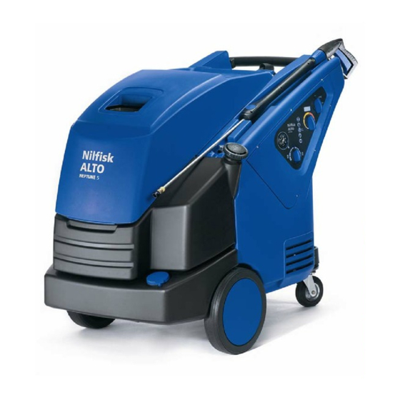
Construction Neptune 5 / 7 In this manual two different models are described: the NEPTUNE 5 and the NEPTUNE 7. The two models are built with the same frame and cabinet. Visually they are different on two points - the height of the heat exchanger and the type of motor pump used. - Page 12 Construction Service side With the service doors open there is free access to all technical parts that require service (Pic. 3.4 and Pic 3.5). Fuel suction pipe Fuel gauge Fuel return pipe Pressure gauge connection Temperature safety switch Flame sensor Fuel nozzle connection Temperature sensor Pic.
- Page 13 Construction Frame 5 / 7 The frames of Neptune 5 and 7 are identical and built up in a straightforward form, all bolted together (see drawings). Fuel return pipe Fuel tank gauge Fuel suction pipe AntiStone tank Fuel tank Inlet valve...
-
Page 14: Pump Oil
Construction Operator side The electric box (Pic. 3.8) contains the control board, the transformer, relays, fuses and connection terminals. The cover plate is mounted with the main switch, the display, the temperature adjustment and five status / warning lights (Pic. 3.6). The cover is sealed around the edge, the manometer and the detergent valve (Pic. - Page 15 Construction Electric system The electric control system is built up around the control board A1 (Pic. 3.10) which is divided into two systems, a 5 VDC system on one side to supply the sensors B8, B4, B6, B1, B9, B7 and on the other side 24 VAC, which supplies the actors (contactor, relay, solenoid valve).
- Page 16 Construction Heat exchanger The heat exchanger is the heat generating part of a hot water machine. It consists of a labyrinth- constructed tube coil, which encloses the combustion chamber. The tube coil is enclosed by a double container with boiler jacket, bottom and top in a sandwich construction, between which the pre-heated air is routed into the combustion chamber.
- Page 17 (axial). Pressure valve Suction valve Stator Rotor Wobble disc Piston The three piston radial pump NP5 used in the Neptune 5 models is a compact unit with motor and pump. Crankshaft Pressure valve Motor Motor shaft Piston Suction valve Neptune_GB_Ver.2.0_10/03...
-
Page 18: Function
Function Operation Detergent valve A / B Display Start cold water mode Start hot water mode Main switch S1 Temperature setting Suction from pump Status indicators Pic. 4.1: Operator panel Detergent Detergent Pressure gauge Connected to water tank If the machine and power supply are o.k. (depending on the electronic set-up) following will happen doing start up: When the main switch S1 is turned on to cold or hot water mode, the machine runs a self test (3 dashes are shown in the display). - Page 19 Function Heat exchanger When the machine is running in hot water mode the fan draws in air and leads it into the side of the heat exchanger around and between the two jackets up to the air distributor. On the way, the air is preheated before it is mixed with the oil spray from the nozzle.
- Page 20 Function C3 pump The C3 four piston axial pump used in the NEPTUNE 7 models Pressure valve Suction valve Wobble disc Stator Rotor Piston The four ceramic pistons are driven by a wobble disc which transforms the rotating power from the rotor into the reciprocating pump pistons.
- Page 21 Function NP5 pump The N 5 three piston radial pump used in the Neptune 5 models Pressure valve Crankshaft Motor Motor shaft Piston Suction valve Three pistons are driven by connecting rods which are attached to a crankshaft which is, in turn, driven by the electric motor.
- Page 22 Function Control Safety Block 1 Fine adjustment screw Low volume adjustment HP hose to boiler Main ajustment nut Low volume spring Flow switch B2. NO Unloader spring Magnet piston Microswitch B4. NC Non-return valve Unloader valve piston Safety valve Unloader valve seat HP outlet from pump Water inlet suction side When the machine is started with a closed spray gun:...
- Page 23 Function Control Safety Block 2 There are four purposes of the Control Safety Block: 1. To secure the machine against an excess of pressure. 2. To ensure a quick start. 3. To reduce the pressure in the pump when in by-pass mode. 4.
- Page 24 Function Sensors / Actors Temperature adjustment Sensors: B1: Temperature sensor at the outlet of the heat exchanger. Controls the combustion (Y1 on/off) according to setting. B2: Flow switch senses the flow out of the pump into the heat exchanger and with B1, controls solenoid Y1 (on/off).
- Page 25 Function Electric system The machine is supplied with main power which is transformed into 8 VAC to supply the microprocessor and sensors and 24 VAC to supply the actors (contactor, relay, solenoid valve). To run the machine on hot water the following must be o.k.: on the front panel S1 and the temperature setting on hot and the spray handle open.
- Page 26 Trouble-shooting Functional requirements 1. Water supply must be able to deliver the needed water at a min. of 1bar pressure. 2. The water inlet temperature must not exceed 40 C (104 F). ° ° 3. The water must be without impurities as for instance floating sands > (50 µ). 4.
- Page 27 15. Fuel level low or water in fuel tank. internal faults require a systematic inspection of the motor pump by an ALTO technician. In order to establish the reason of the fault with certainty, it may be a help to use the yes / no- diagram or the flowchart on page 29.
- Page 28 Trouble-shooting Error codes Cause Symptom Display Outer Inner Check Heat exchanger Ho S t afety temperature switch B3 Wire defective Flow and pressure security adjustment. switch out of Use of long hoses at opens when temp. is higher than adjustment. Switch B3 must be steam with leaky °...
- Page 29 Trouble-shooting Electrical tests Before you change the control board run through these tests: 1. “Power On” Check Turn to cold. Stand-by. Pic. 5.1: PCB A1 ! DC ! ! DC ! 3. “Power Off” Check Check all three phases Disconnect machine from mains power. on K1.
- Page 30 Trouble-shooting Heat exchanger performance The symptom is reduced performance of the pump effect or the heat exchanger effect. The symptom of reduced heat exchanger effect is a lower water outlet temperature than the set value. The possible causes for this are as follows: Scale deposits in heat exchanger tube Scale formation acts as insulation and reduces heat transfer to the water.
- Page 31 Trouble-shooting Pressure Start machine Activate the spray handle with correct nozzle mounted the working pressure o.k. ? Release spray gun the pressure steady? Check Check water supply, the preasure seat of water temperature, steady? unloader valves valve Check Machine O-Rings of is o.k.! non-return and unloader valve...
-
Page 32: Service / Repair
Service / Repair C3 Survey Unloader valve. Page 31 Cylinder head. Page 32 / 33 Cylinder block. Page 34 / 35 Motor and wobble disc. Page 36 / 37 Neptune_GB_Ver.2.0 10/03... - Page 33 Service / Repair Control Safety Block If any pitting or scratches are found on the unloader piston and seat, or on the non-return valve and seat, these parts must be renewed! 20Nm The safety valve has been set at the factory and can’t be adjusted.
- Page 34 Service / Repair C3 Cylinder head 1 Kit (P/N 1119571) Pressure valve LP pressure sleeve Suction valve HP pressure sleeve Kit (P/N 107120700) Kit (P/N 1119310) Dismounting and mounting by hand. Attach the big O-ring using grease. Dismount suction valve seat with a Note position of the casting "smile".
- Page 35 Service / Repair C3 Cylinder head 2 Back-up ring (7) LP-sleeve “rubber” (6) Thrust collar (5) O-Ring (1) Back-up ring (4) HP-sleeve “textile” (3) Nylonring (2) Suction valve Duct Pressure valve Duct Mounting of textile sleeves by means of tool P/N 1220090. It is an advantage if the sleeves have been in a water bath for 3-4 hours before mounting them.
- Page 36 Service / Repair C3 Cylinder block 1 Washer O-Ring Thrust collar Torque moment: 37 Nm Stud Oil sleeve O-Ring (1) LP sleeve (6) Back-up ring (7) Drain the oil. Loosen the 8 nuts gradually and evenly (because of the spring load). Special extra- deep 17 mm box head P/N 1206762 may be used.
- Page 37 Service / Repair C3 Cylinder block 2 Carefully tip out the oil sleeves with an adequate screwdriver and discard them. Be careful not to scratch the surface. Pic. 6.5: Dismounting oil sleeves Before mounting the new sleeves, it will be a good idea to moisten the sleeves with soapy water.
- Page 38 Service / Repair Motor / Wobble disc 1 The motor consists of a stator with windings and a rotor with shaft which is kept in the right place by a bearing in the N bearing cover and the inner needle bearing of the wobble disc in the D bearing cover.
- Page 39 Service / Repair Motor / Wobble disc 2 When mounting the D-bearing cover completely, protect the U- sleeve with tool P/N 1206598 which is placed on the shaft before placing the cover. Tool : 1206598 Pic. 6.8: Mounting D-bearing cover Pic.
- Page 40 Service / Repair NP5 Survey Control Safety Block. Page 39 Valve cover & seals. Page 40 / 41 Motor. Page 43 Pistons & oil seals. Page 42 Pump h ousing Page 43 Neptune_GB_Ver.2.0 10/03...
- Page 41 Service / Repair Control Safety Block If any pitting or scratches are found on the unloader piston and seat, or on the non-return valve and seat, these parts must be renewed! 20Nm 20Nm The safety valve has been set at the factory and can’t be adusted.
- Page 42 Service / Repair NP5 Pump head 1 Water outlet Pressure valve O-Ring (1) O-Ring LP sleeve (3) HP sleeve (4) Support ring (5) Suction valve Thrust collar (2) Duct Brass plug Water inlet O-Ring O-Ring Dismount the brass plug on the cylinder head with a 21mm fixed spanner and remove the valves.
- Page 43 Service / Repair NP5 Pump head 2 & seals Pic. 6.16: Mounting HP sleeve & support ring Pic. 6.15: Dismounting thrust collar 2. When mounting the sleeves and the 1. Be careful when you dismount thrust support ring (Pic. 6.16) remember collar (Pic.
- Page 44 Service / Repair Piston & oilseal To inspect the plunger for cracks: Spray the inside of the plunger with fast evaporating cleaner such as a brake cleansing agent. The brake cleansing agent will take a second longer to evaporate from the crack, thus making the crack visible.
- Page 45 Service / Repair Pump house & motor Replace the motor completely if: 1. One or more windings have burned or broken. 2. Cable connection from motor plug to stator has been broken. 3. Flash-over to frame. 4. Bearings abnormally worn. Replace the pump X completely 1.
- Page 46 Service / Repair Heat exchanger removal With a special designed service crane P/N 301001078 it’s no longer necessary to remove the coil by hand. Just put up the crane to the central tube and disconnect all connections attached to the heat exchanger and burner. Then remove burner and outer heat exchanger cover.
- Page 47 Service / Repair Electrodes / tank meter How to handle the burner insert: - Always remove electordes (18) first while Spring washer dismounting burner insert. - Tighten fuel nozzle (17) only with a hexagonal wrench and a torque of 18 Nm. Otherwise the fuel nozzle can be damaged and a proper combustion can’t be 4 mm...
- Page 48 2. Remove filter with tool and clean it. Quick 3. Clean filter at the pump inlet hose. Neptune 5 Neptune 7 Neptune 5 Neptune 7 Oil filter To clean or replace filter: 1. Unscrew filter cap (1) 2. Clean / replace oil filter (2).
-
Page 49: Adjustment / Test
Adjustment / Test Electronic setup Machine cut off with pressure release. Function used in connection with remote mode. If “2” is on, machine switches off after 20 min. in by-pass mode. A restart is only possible with mainswitch S1. At the same time the ouput of the optional valve Y2 gets power for 10 s to release pressure at the HP outlet. - Page 50 - Close trigger gun and check max. cut-off pressure (see Table 1). If necessary readjust - Lock setscrew (7) with lock nut (9) - Check operating pressure again Operating Pressure 5-25 5-27 5-42 5-49 5-57 7-25 7-63 Table 7.1: Neptune 5 / 7 pressure settings Neptune_GB_Ver.2.0_10/03...
- Page 51 Adjustment / Test Control Safety Block Adjusting microswitch (3): - Switch on machine and open trigger gun. When operating pressure is reached close trigger gun (machine does not shut off) - After loosening lock nut slowly turn adjustment screw (5) to right until machine shuts off. Then turn ½ - ¾ additional turns in the same direction.
- Page 52 (Table 7.2)! Mount the nozzle with a hexagonal wrench and a torque of 18 Nm. 6. Disconnect fuel pressure gauge. Pic. 7.3: Measuring fuel pressure Fuel nozzle Part number NEPTUNE 5-25/27/7-25 1.35 60°H 301001068 NEPTUNE 5-42/49/57 1.75 60°H 301000886 NEPTUNE 7-63 2.50...
- Page 53 Adjustment / Test Combustion Caution! Higher CO concentrations at atmospheric pressure differences, different altitudes or temperatures and low quality of the used fuel can lead to a faster accumulation of soot on the heat exchanger coil. Soot NEPTUNE 11,5 – 12 5,3 –...
- Page 54 Adjustment / Test ALTO AntiStone device The ALTO AntiStone device is set at the factory to water hardness class 2. Adjustment steps: 1. Measure the water hardness or ask your water supply company. Read off setting for ALTO AntiStone from the table below and set the adjusting knob to required position.
- Page 55 Adjustment / Test Electrical connection Some models are equipped with a star delta switch S2 to change between 230 V and 400 V. Caution! Before connecting devices with voltage changeover: Check that the pre-selected voltage on the machine corresponds with the voltage of the electrical installation. Otherwise the electrical devices of the machine can be ?? 230 V / 400 V ?? destroyed!
-
Page 56: Wiring Diagrams
Wiring diagrams Star 71246 L2 L3 Datalogger 5 VDC X4-21 8 VAC X4-23 400 VAC X5-13 X4-17 X5-15 24 VAC X4-19 X5-5 X4-15 X4-13 X5-7 X5-9 X4-9 X4-11 X5-11 X3-1 µP X6-9 X6-11 X3-9 X5-1 X3-5 X5-3 X4-5 X6-1 X4-7 14, 24 X6-3 X4-1... - Page 57 Wiring diagrams phase 71250 Datalogger 5 VDC X4-21 8 VAC X4-23 230 VAC X5-13 X4-17 X5-15 24 VAC X4-19 X5-5 X4-15 X4-13 X5-7 X5-9 X4-9 X4-11 X5-11 X3-1 µP X6-9 X6-11 X3-9 X5-1 X3-5 X5-3 X4-5 X6-1 14, 24 X4-7 X6-3 X4-1 X6-6...
- Page 58 Wiring diagrams Star / Delta 71261 Datalogger 5 VDC L2 L3 X4-21 8 VAC X4-23 X5-13 X4-17 X5-15 24 VAC X4-19 X5-5 X4-15 13 (17) X4-13 X5-7 14 (18) X5-9 X4-9 X4-11 Xma XMb X5-11 X3-1 µP X6-9 X6-11 X3-9 X5-1 X3-5 X5-3...
-
Page 59: Special Tools / Spare Parts
Special tools / Spare parts Special tools Name 17237 Soot pump with filter paper and soot comparison chart 17238 Filter paper (spare) 17239 Soot comparison chart 17241 CO2 test liquid 17242 Exhaust air thermometer (Manual) 17243 Measurement suitcase 17246 Oil-pressure testing 17249 CO measurement equipment with spare test liquid... - Page 60 301001195 Repair kit - CSB (5-57, 7-63) Table 9.2: Spare parts Table 9.2 includes all important repair kits and parts necessary for service and maintenance. For a detailed view have a look in the spare parts list of Neptune 5 / 7 (P/N 301001054). _10/03 Neptune_GB_Ver.2.0...
- Page 61 Special tools / Spare parts Further material Name 41455 Grease (-15 °C till +130 °C), 50 g tube Table 9.3: Further material To lubricate sleeves, O-Rings and other parts always use the grease in table 9.3. Never use grease containing silicon for parts that get in touch with water! _10/03 Neptune_GB_Ver.2.0...