Table of Contents
Advertisement
Advertisement
Table of Contents

Related Manuals for Scytek electronic G777


Summary of Contents for Scytek electronic G777
- Page 1 G777,G27 A777,A20 VEHICLE SECURITY SYSTEM PRODUCT MANUAL...
- Page 2 L L i i m m i i t t e e d d L L i i f f e e t t i i m m e e W W a a r r r r a a n n t t y y This vehicle security system is warranted to the original purchaser, to be free from defects in material and workmanship.
-
Page 3: Table Of Contents
T T a a b b l l e e o o f f C C o o n n t t e e n n t t s s About Your System ............Page 1 2-way LCD Remote Transmitters . -
Page 4: System Contents
Status LED • Coded Override/Valet Switch, G27, A20 • Coded Override/ Valet Switch /LED/ Call Button built into the antenna, G777, A777 • Options and Accessories This ScyTek system includes several optional inputs and outputs allowing the creation of a completely personalized security and convenience system by offering many optional features . -
Page 5: About Your System
In order to change the battery, first slide the battery door locking pin to the side. Carefully slide the battery cover downward until it is free. While replacing the battery make sure that the positive and negative terminals are positioned correctly, then carefully reassemble the transmitter case. Page 2 - G777,G27,A777,A20... -
Page 6: Way Lcd Remote Transmitters
3. Press Button 3 until the desired minute is displayed. The button may be held down to scroll faster. 4. When the desired time is displayed; press Button 5 to turn ON the daily start time press Button 1 to turn OFF the daily start time G777,G27,A777,A20 - Page 3... -
Page 7: Adding/Replacing 2-Way Lcd Transmitters
1. Press and hold Button 5 until the display shows DEG ·The transmitter will beep twice. 2. Release Button 5. · The transmitter will beep four times. · The LCD panel will display the temperature inside the vehicle Page 4 - G777,G27,A777,A20... -
Page 8: Transmitter Programming
The transmitter will beep 9 times. 2. Release Button 5. The transmitter will beep once. The LCD transmitter will beep 5 times and display “on” if the sounds are enabled or vibrate and display "off" for the Remote to vibrate. G777,G27,A777,A20 - Page 5... -
Page 9: Lcd Icon Description
3. Press Button 1 on the first transmitter, then on the second transmitter. · The siren will chirp once for each transmitter learned. 4. Turn off the ignition key. 5. The siren will chirp 3 times to indicate the system has exited programming mode. Page 6 - G777,G27,A777,A20... -
Page 10: Remote Transmitters
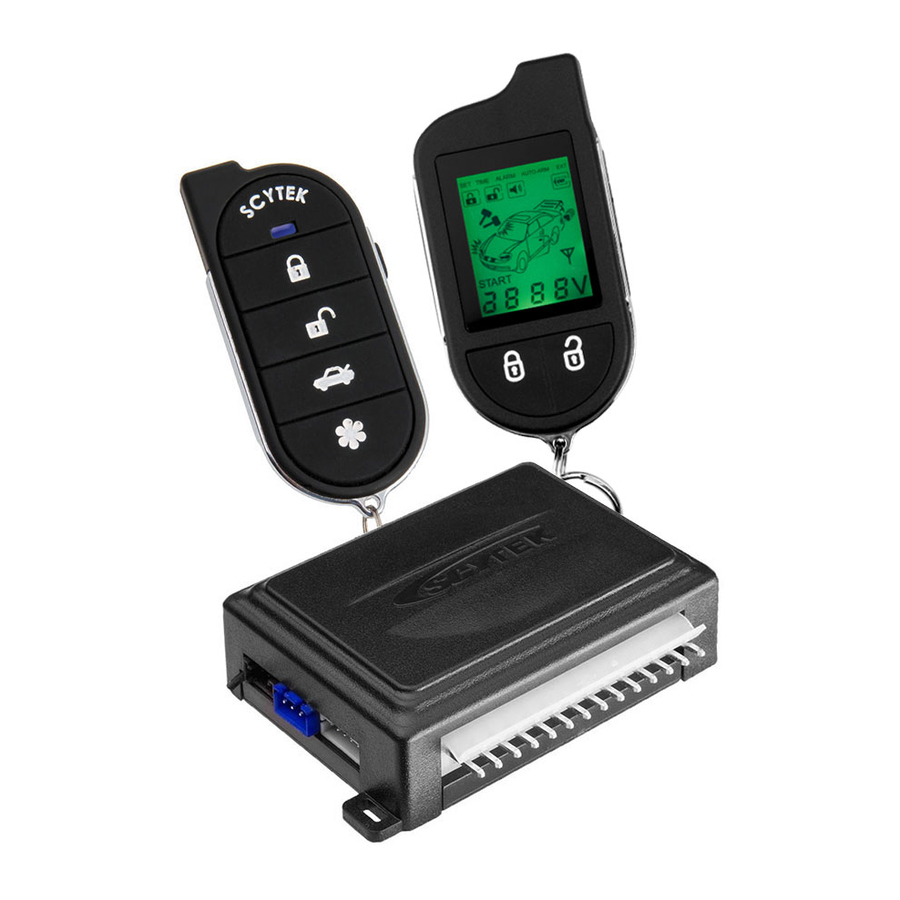
Button 5 G777,G27 A777,A20 The G777,G27,A777,A20 is supplied with 5-button Remote Transmitter used to control system operations. Button 1 Arms and Locks* the system and when held for 5 seconds, activates the system’s Panic feature. Button 1 also locks the doors when the system is in Valet Mode. -
Page 11: Adding/Replacing Transmitters
Shift button twice and the desired function button. Battery Replacement Your Remote Transmitter uses battery type 2016 for G777,G27 and 23A for A777,A20 which will require replacement in time. Depending on the amount of use, the battery may last up to 24 months or more before it needs replacement. -
Page 12: System Operation
* During Disarming, if the system was triggered while away from the vehicle, the siren will chirp 3 times, the parking lights will flash 3 times, and the LED will flash to indicate triggered zone. See Tamper Alert for zone listing. ** If the optional Dome Light Activation Feature is installed. G777,G27,A777,A20 - Page 9... -
Page 13: Tamper Alert
· The siren will chirp. · The parking lights will flash. · The doors will lock.* · The status LED will begin flashing. 4. The system is now armed. * If the Passive Locking feature is selected. Page 10 - G777,G27,A777,A20... -
Page 14: Panic Mode
· The siren will provide one long chirp, indicating that you have entered Programming. 3. Press the valet switch 4 times. · The siren will chirp each time the valet switch is pressed. 4. Within 5 seconds, press Button 3 on the transmitter. G777,G27,A777,A20 - Page 11... -
Page 15: Automatic Rearming
DRIVER CALLING/PAGE FEATURE The G777, A777, is equipped with a Driver Calling or Paging feature that allows the system to send a page to the LCD transmitter in the event the transmitter has been misplaced or lost (within 1500 feet) To activate the Driver Calling/Page feature: 1.Locate the Valet/Emergency Override button in your vehicle (Ask your installation shop) -
Page 16: Extended Features
Auxiliary Function Outputs The G777,G27,A777,A20 system is equipped with 2 Auxiliary Outputs allowing the convenience features of the system to be further expanded. These outputs can be used to add a number of optional features such as: power trunk release, remote engine start, power window activation, power sunroof control, and more. -
Page 17: System Installation
3. Verify with the owner, the mounting locations for all visible components, including the LED and Override switch. 4. Verify with the owner, the optional features of the G777,G27,A777,A20 and the functions that must be programmed during installation. 5. Inspect and perform a function test of all vehicle systems before and after the installation. -
Page 18: Mounting The Control Unit
During proper operation, the shock sensor will detect impacts to the vehicle only and will not usually be triggered by slow rocking movements of the vehicle like those caused by wind. G777,G27,A777,A20 - Page 15... -
Page 19: System Wiring
This type of door circuit is usually found on Ford vehicles. Pin 14 GREEN WIRE: Negative door trigger Input (-). Connect to the door switch circuit wire that shows ground when the door is open. Page 16 - G777,G27,A777,A20... -
Page 20: Plug-In Connectors
Parking Light Output. Selects the polarity (+/-) for the output of the on-board Parking Light relay. Left Pin + Center Pin = positive Right Pin + Center Pin = negative Default setting shown G777,G27,A777,A20 - Page 17... -
Page 21: System Programming
The Ignition Door Locking feature may be programmed to unlock all doors or the driver’s door only. If driver’s door only is selected, the optional Passenger Unlock feature must be connected. (See Two Stage Door Lock Diagrams) Page 18 - G777,G27,A777,A20... - Page 22 18. Auxillary 2 Output Selectable. Selects either Auxillary 2 output, starter output or ignition output. 19. Extended Parking Lights. When selected, the parking lights will remain ON for 30 seconds after disarming the system. G777,G27,A777,A20 - Page 19...
-
Page 23: Branch Table
Enabled with Validation, factory remote will disarm only when the Factory disarm validation input is connected to the horn or parking lights. (this input must be activated within a second upon unlock by the factory remote). Page 20 - A777, A20, G777, G27... -
Page 24: Door Lock Diagrams
15 Minutes 25 Minutes Automatic Start Mode 2 Hours 1 Hour Crank Time Normal Extended Super Extended Engine Sense Mode Monitor Off Data Bus Engine Type Diesel Turbo Mode Factory Alarm Upgrade Disabled Enable with validation Enable G777,G27,A777,A20 - Page 21... -
Page 25: Two Stage Door Lock Diagrams
D D o o o o r r L L o o c c k k D D i i a a g g r r a a m m s s Follow the diagrams below for connecting basic door lock systems. For Two Stage door lock systems (separately unlocks driver and passenger doors) see following pages. Negative Trigger Positive Trigger Reverse Polarity Vacuum Adding Actuators Page 22 - G777,G27,A777,A20... - Page 26 T T w w o o S S t t a a g g e e D D o o o o r r L L o o c c k k D D i i a a g g r r a a m m s s The G777,G27,A777,A20 is equipped with a dedicated Passenger Unlock output allowing Two Stage Door Lock operation.
- Page 27 T T w w o o S S t t a a g g e e D D o o o o r r L L o o c c k k D D i i a a g g r r a a m m s s c c o o n n t t ’ ’ d d Two Stage Reverse Polarity Two Stage Adding Actuators Page 24 - G777,G27,A777,A20...
- Page 28 Operation is subject to the following two conditions: 1) This device may not cause harmful interference. 2) This device must accept any interference received, including interference that may cause undesired operation Call,Emergency Override,Valet Switch LED Light G777,A777 G777,G27,A777,A20 - Page 25...
- Page 29 Violet (+) Door Trigger Input, zone 4 Green (-) Door Trigger Input, zone 4 Receiver Antenna G777/A777 Green Factory Alarm Upgrade Arm Input (+) Harness Optional Factory Alarm Upgrade Disarm Validation Input (+) Blue Factory Alarm Upgrade Disarm Input (+)
Need help?
Do you have a question about the G777 and is the answer not in the manual?
Questions and answers