MTD 240 Series Operator's Manual
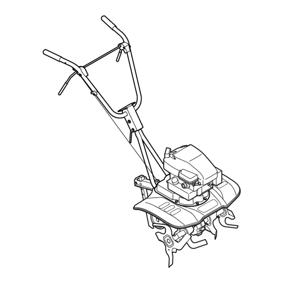
World tiller
Hide thumbs
Also See for 240 Series:
- Operator's manual (41 pages) ,
- Operator's manual (18 pages) ,
- Operator's manual (32 pages)
Table of Contents
Advertisement
Quick Links
Download this manual
See also:
Operator's Manual
Safe Operation Practices • Set-Up • Operation • Maintenance • Service • Troubleshooting • Warranty
O
'
M
peratOr
s
anual
World Tiller — Series 240
WARNING
READ AND FOLLOW ALL SAFETY RULES AND INSTRUCTIONS IN THIS MANUAL
BEFORE ATTEMPTING TO OPERATE THIS MACHINE.
FAILURE TO COMPLY WITH THESE INSTRUCTIONS MAY RESULT IN PERSONAL INJURY.
MTD LLC, P.O. BOX 361131 CLEVELAND, OHIO 44136-0019
Printed In USA
Form No. 769-05429C
(April 22, 2010)
Advertisement
Table of Contents

Related Manuals for MTD 240 Series


Summary of Contents for MTD 240 Series
- Page 1 READ AND FOLLOW ALL SAFETY RULES AND INSTRUCTIONS IN THIS MANUAL BEFORE ATTEMPTING TO OPERATE THIS MACHINE. FAILURE TO COMPLY WITH THESE INSTRUCTIONS MAY RESULT IN PERSONAL INJURY. MTD LLC, P.O. BOX 361131 CLEVELAND, OHIO 44136-0019 Printed In USA Form No. 769-05429C...
-
Page 2: Table Of Contents
Choose from the options below: ◊ Visit us on the web at www.mtdproducts.com ◊ Call a Customer Support Representative at (800) 800-7310 or (330) 220-4683 ◊ Write to MTD LLC • P.O. Box 361131 • Cleveland, OH • 44136-0019... -
Page 3: Important Safe Operation Practices
Important Safe Operation Practices WARNING! This symbol points out important safety instructions which, if not followed, could endanger the personal safety and/or property of yourself and others. Read and follow all instructions in this manual before attempting to operate this machine. Failure to comply with these instructions may result in personal injury. - Page 4 When practical, remove gas-powered equipment After striking a foreign object, stop the engine, disconnect from the truck or trailer and refuel it on the ground. the spark plug wire and ground against the engine. If this is not possible, then refuel such equipment on Thoroughly inspect the machine for any damage.
-
Page 5: Spark Arrester
Spark Arrester If the fuel tank has to be drained, do this outdoors. Observe proper disposal laws and regulations for gas, oil, WARNING! This machine is equipped with an etc. to protect the environment. internal combustion engine and should not be used According to the Consumer Products Safety Commission on or near any unimproved forest-covered, (CPSC) and the U.S. - Page 6 Safety Symbols This page depicts and describes safety symbols that may appear on this product. Read, understand, and follow all instructions on the machine before attempting to assemble and operate. Symbol Description READ THE OPERATOR’S MANUAL(S) Read, understand, and follow all instructions in the manual(s) before attempting to assemble and operate WARNING—...
-
Page 7: Assembly & Set-Up
Assembly & Set-Up Contents of Carton • One Tiller • One 20 oz. bottle SAE 30W oil • One Tiller Operator’s Manual • One Engine Operator’s Manual NOTE: The tiller is shipped without gasoline or oil in the engine. Position the upper handle onto the lower handle. See Fig. Fill up gasoline and oil as instructed in the accompanying engine 3-2. - Page 8 Set-Up Insert the clutch cable handle fitting into the hole on the right side of the upper handle. See Fig. 3-3. Gas & Oil Fill-Up Service the engine with gasoline and oil as instructed in the separate engine manual packed with your tiller. Read the instructions carefully.
-
Page 9: Controls
Controls and Features Tine Clutch Control Recoil Starter Clutch Cable Handlebar Height Adjustment Depth Stake Back of Tiller Tines Rear Wheel Rear Wheel Depth Stake Figure 4-1 Rear Wheel with Depth Stake Tine Clutch Control The rear wheel can be raised and lowered for transport and The clutch control lever is located on the upper handle. -
Page 10: Operation
Operation The working depth of the machine may be predetermined by WARNING! Read, understand, and follow all setting the depth stake so that the wheels are about four inches instructions and warnings posted on the machine from the ground when the tines and depth stake are resting on and in this manual before operating. - Page 11 In some soils, the desired depth is obtained the first time over For proper decaying action, fertilizer should be applied and the garden. In other soils, the desired depth is obtained by going worked in with the mulch materials. Breaking up leaves and straw over the garden two or three times.
-
Page 12: Maintenance & Adjustment
Maintenance & Adjustments Adjustments WARNING! Before inspecting, cleaning or servicing the tiller, shut off the engine and wait for all moving Tine Width parts to come to a complete stop. Disconnect the spark plug. Failure to follow these instructions The tilling width of the unit is 22 inches. Tilling width can properly can result in serious personal injury or increase to 24 inches by removing the clevis and cotter pins, property damage. -
Page 13: Depth Stake
Depth Stake The depth stake acts as a brake for the tiller and controls the depth and speed at which the machine will operate, Figure 6-2. Remove the clevis and cotter pins, raise or lower the depth stake, then reattach pins to secure. Clevis Pin Cotter Pin Figure 6-2... -
Page 14: Engine Maintenance
Engine Maintenance WARNING: Periodic inspection and adjustment of the engine is essential if Shut off the engine before performing high level performance is to be maintained. Regular maintenance any maintenance. To prevent accidental start-up, will also ensure a long service life. The required service intervals disconnect the spark plug boot. - Page 15 Oil Service Oil Recommendations • Check oil level regularly. NOTE: This engine is shipped without gasoline or oil in the engine. Running the engine with insufficient oil can cause • Be sure correct oil level is maintained. Check every five serious engine damage and void the engine warranty.
- Page 16 Remove the thumb screw and the air cleaner cover. WARNING: If the engine has been running, the Remove the elements and separate them. See Fig. 10-2. muffler will be very hot. Be careful not to touch the Replace paper element when dirty or damaged. Clean muffler.
- Page 17 Fuel Filter Service Storage The fuel filter cannot be cleaned and must be replaced once a Engines stored between 30 and 90 days need to be treated with year or every 100 operating hours; more often if run with old a gasoline stabilizer and engines stored over 90 days need to be gasoline.
-
Page 18: Service
Replace with Lock Nut a factory-approved OEM belt. See the retailer from which you purchased your tiller, an authorized MTD Service Dealer, or call 1-800-800-7310 for information regarding price and availability. Remove the belt cover and engine by removing the six... -
Page 19: Troubleshooting
Troubleshooting Problem Cause Remedy Engine Fails to start 1. Spark plug wire disconnected 1. Connect wire to spark plug 2. Fuel tank empty or stale fuel 2. Fill tank with clean, fresh gasoline 3. Throttle control lever (if equipped) not in 3. -
Page 20: Illustrated Parts List
Illustrated Parts List... - Page 21 Handle, Frame & Wheel Assembly Ref. Part Number Description Ref. Part Number Description 749-04265-0638 Depth Stake Tube 649-04030-0638 Upper Handle 711-04520 Axle Shaft 710-0136 Hex Head Cap Screw, 1⁄4-20 x 1.75 710-1007 Self Tapping Screw, 3⁄8-16 x 1.50 649-04029-0638 Lower Handle 911-0415 Clevis Pin 710-04398...
- Page 22 Engine Model - 1P65LHA...
- Page 23 Engine Model - 1P65LHA Part No. Description Part No. Description 710-04744 Self-Tapping Bolt,Hilo #12-16 X 1.00" 712-04212 Governor Arm Nut M6 951-11678 Governor Arm 931-04437 Engine Shroud 710-04908 Governor Arm Bolt 951-10299A Recoil Starter Assembly 951-11679 Governor Arm Shield 712-04212 Nut M6 X 10 Mm 951-10619 Choke Control...
- Page 24 Engine Model - 1P65LHA Part No. Description Part No. Description 710-04903 Fuel Drain Plug 951-10300 Fuel Cap Assembly — Fuel Cap 951-11684 Carburetor Gasket — Sponge Insert 951-11527 Carburetor Insulator — Vent Gasket 951-11528 Carburetor Insulator Gasket 710-05093 Carb Stud M6x92 951-11520 Breather Hose Assembly 710-04982...
- Page 25 Engine Model - 1P65LHA Part No. Description Part No. Description — 951-10298 Air Cleaner Kit — 951-10846 Cylinder Head — Pre-Cleaner — Head Bolt M8×54 — Air Filter — Intake Valve Seal — 951-10882 Air Cleaner Housing Ass'y — Valve Cover Gasket —...
- Page 26 Engine Model - 1P65LHA Part No. Description Part No. Description — 951-11689 Short Block — 951-10334 Oil Fill Tube Assembly — Bolt M6×14 — Oil Fill Tube — Breather Cover Plate — Oil Fill Tube O-Ring — Breather Gasket — 951-10313 Valve Kit —...
- Page 27 Notes...
-
Page 28: Warranty
MANUFACTURER’S LIMITED WARRANTY FOR The limited warranty set forth below is given by MTD LLC with c. Routine maintenance items such as lubricants, filters, blade respect to new merchandise purchased and used in the United States sharpening, tune-ups, brake adjustments, clutch adjustments,...
Need help?
Do you have a question about the 240 Series and is the answer not in the manual?
Questions and answers