Advertisement
Quick Links
Safety • Assembly • Operation • Tips & Techniques • Maintenance • Troubleshooting • Parts Lists • Warranty
A
O
A
AL
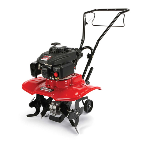
Model241shown
Front Tine Tiller -- Model Series 240
IMPORTANT
READ SAFETY
RULES AND INSTRUCTIONS
CAREFULLY
BEFORE
OPERATION
Warning: This unit isequippedwith an internal combustionengineand shouldnot be usedon or nearany unimproved forest-covered, b rush-
coveredor grass-covered land unlesstheengine'sexhaustsystemis equippedwith a sparkarrestermeetingapplicablelocalor statelaws(if any).
If a sparkarresterisused,it shouldbe maintainedineffectiveworkingorder by the operator.In theState of Californiathe aboveisrequiredbylaw
(Section4442 of the CaliforniaPublicResources Code). Otherstatesmay havesimilarlaws.Federallaws applyon federallands.A sparkarrester
for the muffleris availablethroughyour nearestengineauthorizedservicedealeror contactthe servicedepartment,RO. Box361131 Cleveland,
Ohio 44136-0019.
PRINTEDIN U.S.A.
MTD LLC, P.O. BOX 361131 CLEVELAND, OHIO 44136-0019
FORMNO.769-02153A
3/2/2006
Advertisement

Related Manuals for MTD 21A-241E052


Summary of Contents for MTD 21A-241E052
- Page 1 If a sparkarresterisused,it shouldbe maintainedineffectiveworkingorder by the operator.In theState of Californiathe aboveisrequiredbylaw (Section4442 of the CaliforniaPublicResources Code). Otherstatesmay havesimilarlaws.Federallaws applyon federallands.A sparkarrester for the muffleris availablethroughyour nearestengineauthorizedservicedealeror contactthe servicedepartment,RO. Box361131 Cleveland, Ohio 44136-0019. FORMNO.769-02153A 3/2/2006 PRINTEDIN U.S.A. MTD LLC, P.O. BOX 361131 CLEVELAND, OHIO 44136-0019...
- Page 2 Serial Number vided to the right. Youcan locatethe model plate by lookingat the rearof the tine shield. This information is importantfor use when visiting the manufacturer's MTD LLC web site, obtainingassistancefrom the Customer P.O= BOX 361131 Support Department,or when contacting an autho-...
- Page 3 Safety Labels Found On Your Tiller i_ii_ _ i i i _i I i_ _ ii_ TO AVOID SERIOUS iNJURY 1. READTHE OPERATOR'S M ANUAL. Labels 2. KNOWLOCATION AND FUNCTIONS OF ALL CONTROLS. 3. KEEPALLSAFETYDEVICES ANDSHIELDS iN PLACEANDWORKING. 4. NEVERALLOWCHILDRENOR UNINSTRUCTED ADULTSTO OPERATE TILLER.
- Page 4 WARNING: Engine Exhaust, some of its constituents, and certain vehicle compo- nents contain or emit chemicals known to State of Californiato cause cancer and birth defects or other reproductiveharm. DANGER: This machine was built to be operated according to the rules for safe operation in this manual.
- Page 5 16.Do not overloadmachinecapacityby attemptingto till soil to Your Responsibility deep at too fast of a rate. 1. Restrictthe use of this power machineto personswho read, 17. Ifthe machineshould start makingan unusualnoise or understand,andfollowthe warningsand instructionsinthis manualand on the machine. vibration,stop the engine,disconnectthe spark plug wire and groundit againstthe engine.Inspectthoroughlyfor 2.
- Page 6 Assembly 4. Insert left end of tine clutch control into the 1. Removethe star handle knobs and carriage hole on the left side of the upper handle, boltsfrom the lower handle, Figure 3-1. Figure 3-3. Assembly Standbehindthe tiller as if you weregoingto operate it.
- Page 7 6. Squeeze t hetineclutchcontrol inward. Insert r ightendintotheholeontheright s ide oftheupper h andle, F igure 3-5. Stand behind the tiller as if you were goingto operate it. Yourright hand correspondsto the right side of the tiller; your left handcorrespondsto the left side of the tiller.
- Page 8 Know Your Tiller Clutch Cable Rear Wheel with Depth WARNING Stake The tit _: is a safety device'Never attempt to bypass its operation, Use extremecarewhen Figure4-1:The majorparts of the tiller (model241 shown). handling gaso ne Gasoline is extremely f ammablo and t he Vapors follow all instructions and warnings ARNING:Read,understand, and...
- Page 9 manyotheruseful laborsavingtasks in the garden.After ARNING: Read,understand, and follow engineis runningand appropriatespeedset on throttle all instructions and warningspostedon the (if equipped),squeezefine clutchcontrol(see Figure4-1) machineand in this manual beforeoperating. againstupperhandleto engagethe fine drive.Release the leverto stopthe tines from turning. Before Starting Wheel Position Gas And Oil Fill-Up Thetiller isshippedwith the wheeladjustedsuchthat the...
- Page 10 Fortilling, thedepth stakemustbe loweredand the wheelmustbe raised,Figure4-4. By increasingthedepthof thedepth stake,theforward speedof the machineis reducedand the workingdepth is increased.Whenthe depthstakeis raised,the working depthof the machineis reducedand the forwardspeed is increased.The workingdepthof the machinemay be predetermined by settingthedepthstakeso that the wheelsare aboutfourinches fromthe groundwhenthe tines and depthstakeare restingon the ground.This ¸...
- Page 11 will be free of hard untilledspots,allowinga betterstand of grassto grow.The tiller is very usefulfor looseninghard soil for excavation with a shovel;Notedious handworkwill be necessary.Yourtiller maybe usedfor mixingcompost in the pile or for mixingit with the soil in yourgarden.This shouldbe doneafter the soil has beenbrokento thefull workingdepth.The compostshouldbe workedin to a depthof six to seveninches.This may be done by workingthe lengthof the gardenand then by makingseparatepassesacrossits width.Theadditionof decayedorganicmatterwill substantiallyincreasethefertility of yourgarden.For properdecayingaction,fertilizershouldbe appliedand workedin...
- Page 12 Making Adjustments Warning: Disconnect the spark plug wire and ground it against the engine before performing any adjustments. Engine Adjustment Refer to the separate engine manual for engine ,€ 24-inch adjustment instructions. Tine Width Adjustment The tilling width of the unit is22 inches. Tilling width can increase to 24 inches by removing the clevis and cotter pins, sliding each outer manualmaycover...
- Page 13 Replacing the Belt nectspark plug, and groundagainst _LIl_lLik, l=WARNING: Alwaysstop engine,discon- Yourtillerhas beenengineeredwith a belt madeof engine beforecleaning,lubricating or specialmaterialfor longerlifeand betterperformance. performingany maintenance on your It shouldnotbe replacedwith an off-the-shelfbelt. See machine. the retailerfrom whichyou purchasedyourtiller,an authorizedMTDServiceDealer,or call 1-800-800-7310 Engine for information regardingpriceand availability.
- Page 14 Problem Cause Remedy Engine fa! s tO start wi!e d ! connect wire to spa[k I 2 Fue tankemptyorstaefue 2 F tankwthcean freshgaso ne 3. Throttle control!evernot in correct 3, Movethrottle leverto start position. sta_ingPosition(i! equipped)position Chokenot n ON post on. 5: clean fuel line.
- Page 15 Off-Season Storage Referto the enginemanualfor correctenginestorage if the tillerwill not be usedfor a period longerthan30 instructions. days,the followingstepsshouldbe taken to preparethe tiller for storage. Wipetines with oiled ragto preventrust. Storetiller in a clean, dry area.Do not storenext to Cleanthe exteriorof engineand the entiretiller corrosivematerials,such as fertilizer.
- Page 17 749-04282 UpperHandle 720-04072 StarHandle Knob 749-04281 LowerHandle 710-04398 FlangeScrew5/16-18x 7.5 754-04123 Belt Parts List 756-04163 idler Pulley 748-04125 ShoulderSpacer 686-04080 IdlerBracket 712-04065 FlangeLock Nut:3/8-16 10 710-0654A TT Screw3/8-16x 1.00 11 786-04303 Frame 12 710-0514 HH CapScrew3/8-16x 1.00 _FACTORY PARTS 13 732-0418 ExtensionSpring To order 14 738-04139...
- Page 18 Notes Use this page to take notes. _ i_ill i_ii i_iii_ _ I_...
- Page 19 Notes Use this page to take notes.
- Page 20 To locate the dealer in your area, check your Yellow Pages, lasts,sothe aboveexclusions or limitations m aynot applyto you. or contact MTD LLC at RO. Box 361131,Cleveland, Ohio 44136- In no event shallrecoveryof any kindbe greaterthanthe amountof the 0019, or call 1-800-800-7310 or 1-330-220-4683 or log on to our purchasepriceof the productsold.Alterationof safety features of...
Need help?
Do you have a question about the 21A-241E052 and is the answer not in the manual?
Questions and answers
Valves not lifting off oof seat.