Advertisement
Table of Contents
- 1 Limited Warranty
- 2 Installation
- 3 Location
- 4 Mounting
- 5 Electrical Connections
- 6 Tuning the Antenna for Optimum SWR
- 7 External Speaker
- 8 Programming Jack
- 9 Public Address
- 10 Operation Guide
- 11 Alternate Microphones and Installation
- 12 Function Menu Navigation
- 13 PRG Menu Navigation
- 14 Navigation Shortcuts
- Download this manual
Advertisement
Table of Contents

Related Manuals for Stryker SR-955HPC


Summary of Contents for Stryker SR-955HPC
-
Page 2: Limited Warranty
This warranty is non-transferable. This limited warranty is subject to repair or replacement of defective components only. This warranty is void if the radio has been tampered with or misused. If your Stryker Radios needs repair any time during the (3) year warranty period please visit our website: www.StrykerRadios.com to obtain an RA number or call 910-221-1086 between... - Page 3 Electrical Connections INSTALLATION The Stryker SR955 is designed to work on any 13.8 volt DC, negative 1. Contents ground electrical source. The condition of a vehicle’s electrical system Unpack and inspect your Stryker SR-955HPC for missing or can have a profound affect on the performance of the radio. A low damaged Components.
- Page 4 Our programming software is available for Set your Stryker radio to your desired operating frequency or the download via our website. center of the range of frequencies you plan to use. Press the PTT Public Address (Press-To-Talk) switch, and tap the antenna (making it shorter).
- Page 5 Microphone Input: The Stryker SR955 accepts microphones with a This switch controls the "roger beep" circuitry. Simply put the female 4 pin connector. For further wiring information please see the roger beep is a tone that sounds when a radio operator un-keys their next page of this manual.
- Page 6 Microphone Gain: Adjusts the microphone gain in the transmit and PA modes. This controls the gain to the extent that full talk power is available several inches away from the microphone. RF Gain: This control is used to reduce the gain of the RF (receive) amplifier under strong signal conditions.
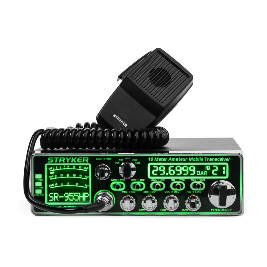
- Page 7 OPERATION GUIDE For detailed descriptions of all functions please see page. Function Menu Button Monitor (Talkback) RF Power Output Control Mode Selector Control Dimmer Switch Hi-Cut Receive Filter Roger Beep Switch Program Switch CTCSS Switch S T R Y K E R Clarifier Mode 10 Meter Amateur Mobile Transceiver Channel Display...
-
Page 8: Alternate Microphones And Installation
ALTERNATE MICROPHONES AND INSTALLATION Before beginning the actual wiring, read carefully the circuit and wiring information provided with the microphone you select. Use the minimum For best results, the user should select a low-impedance dynamic heat required in soldering the connections. Keep the exposed wire type microphone or a transistorized microphone. - Page 9 The function menu allows you to customize many features as well as radio would stop transmitting automatically and the speaker will emit a controls that your Stryker SR-955HP has to offer. To access the function voice prompt until the PTT key is released. Then, the radio can transmit menu press and hold the FUNC Button for approximately two seconds again.
- Page 10 OFF: When OFF is selected, the Power Supplying Voltage is disabled. Default: ON LCD: This option lets you choose if you’d like to display the following on the LCD meter. The first option is to display the model name of the radio, the second option will display the DC voltage present at the power jack and the third option will display the model name during receive and the voltage during transmit.
Need help?
Do you have a question about the SR-955HPC and is the answer not in the manual?
Questions and answers