Sign In
Upload
Download
Table of Contents
Contents
Add to my manuals
Delete from my manuals
Share
URL of this page:
HTML Link:
Bookmark this page
Add
Manual will be automatically added to "My Manuals"
Print this page
×
Bookmark added
×
Added to my manuals
Manuals
Brands
Stryker Manuals
Transceiver
SR-497hpc
User manual
Stryker SR-497hpc User Manual
10 meter hf amateur mobile transceiver
Hide thumbs
1
2
3
4
5
6
7
8
9
10
11
12
page
of
12
Go
/
12
Contents
Table of Contents
Bookmarks
Table of Contents
Limited Warranty
Electrical Connections
Antenna Connections
Tuning the Antenna for Optimum SWR
External Speaker
Public Address
Alternate Microphones and Installation
Advertisement
Quick Links
1
Electrical Connections
2
Tuning the Antenna for Optimum Swr
Download this manual
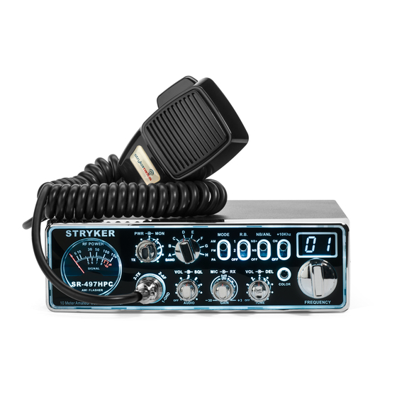
SR-447HPC
&
SR-497HPC
AM/FM/PA
10 Meter HF Amateur Mobile Transceiver
USER'S MANUAL
READ THIS MANUAL BEFORE OPERATION
Table of
Contents
Previous
Page
Next
Page
1
2
3
4
5
Advertisement
Table of Contents
Need help?
Do you have a question about the SR-497hpc and is the answer not in the manual?
Ask a question
Questions and answers
Related Manuals for Stryker SR-497hpc
Transceiver Stryker SR-955HPC User Manual
(12 pages)
Transceiver Stryker SR440-HP User Manual
10 meter hf amateur mobile transceiver (3 pages)
Transceiver Stryker SR-490HP Manual
(9 pages)
Transceiver Stryker SR-89MC User Manual
(15 pages)
Transceiver Stryker SR-447HPC User Manual
10 meter hf amateur mobile transceiver (12 pages)
Transceiver Stryker SR-447HPC2 User Manual
10 meter radio (9 pages)
Transceiver Stryker SR-25MC User Manual
10-meter amateur radio full featured ultra compact am & fm 20+ watts pep, 7 color display & rugged quality (15 pages)
Transceiver Stryker SR-655HPC User Manual
10 meter radio (10 pages)
Transceiver Stryker SR-477HPC2 User Manual
(11 pages)
This manual is also suitable for:
Sr-447hpc
Table of Contents
Print
Rename the bookmark
Delete bookmark?
Delete from my manuals?
Login
Sign In
OR
Sign in with Facebook
Sign in with Google
Upload manual
Upload from disk
Upload from URL


Need help?
Do you have a question about the SR-497hpc and is the answer not in the manual?
Questions and answers