Table of Contents
Advertisement
Quick Links
INTRODUCTION
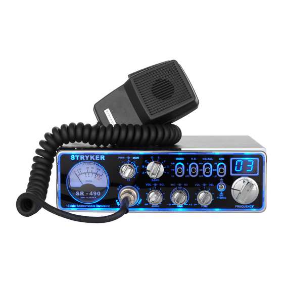
Congratulations on your purchase of a Stryker 10 meter mobile amateur transceiver.
Your Stryker is designed to provide years of enjoyment and trouble-free service. There
are many features and functions designed into this transceiver. To ensure that your
investment is enjoyed to its fullest extent, please take a few moments and thoroughly
read this manual.
LIMITED WARRANTY
Stryker Amateur Radio warrants this product to be free of defects for a period of one
(1) year from the original date of purchase. This warranty is non-transferable. This
limited warranty is subject to repair or replacement of defective components only. This
warranty is void if the radio has been tampered with or misused. If your Stryker
Radios needs repair any time during the (1) year warranty period please visit our
website:
www.StrykerRadios.com
tween the hours of 10 a.m. – 5 p.m. eastern standard time. If you do need service
after your warranty has expired you can still send your radio to us for repair. Our rates
are very reasonable and you can rest assured that your radio will be fixed correctly.
IMPORTANT: RETAIN YOUR SALES RECEIPT
You will need to include a copy of your original sales receipt along with your radio
when sending it in for warranty repair.
INSTALLATION
1. Contents
Unpack and inspect your Stryker SR-440HP for missing or damaged
Components.
Quantity
Description
1
Stryker SR-440HP Transceiver
1
Microphone
1
DC Power Cord with Inline Fuse
1
Mounting Bracket with Hardware
1
Microphone Hanger with Hardware Set
to obtain an RA number or call 910-221-1086 be-
1
Advertisement
Table of Contents

Related Manuals for Stryker SR-490HP


Summary of Contents for Stryker SR-490HP
- Page 1 LIMITED WARRANTY Stryker Amateur Radio warrants this product to be free of defects for a period of one (1) year from the original date of purchase. This warranty is non-transferable. This limited warranty is subject to repair or replacement of defective components only. This warranty is void if the radio has been tampered with or misused.
-
Page 2: Installation
Electrical Connections The Stryker SR440-HP is designed to work on any 13.8 volt DC, negative ground electrical source. The condition of a vehicle’s electrical system can have a profound affect on the performance of the radio. A low battery, worn generator/alternator, or poor voltage regulator will seriously impair the performance of the transceiver. -
Page 3: Antenna Connections
Antenna Connections The Stryker SR440-HP has a jack in the rear for a standard PL-259 antenna plug. If you are looking for the most range for your transmission, use a vertically polarized, quarter-wave length antenna. If antenna height is a problem, you may use a shorter, loaded-type whip antenna although you can expect some loss of transmission range. -
Page 4: External Speaker
Tuning the Antenna for Optimum SWR CONTINUATION 3. The whip is easily cut by filing a notch all the way around, then breaking the piece off with pliers. NOTE The proper setting is achieved when the SWR is 1.5 or below and when it has the same reading for the low and high frequencies in the range you plan to use. - Page 5 OPERATION GUIDE For detailed descriptions of all functions please pages 6-7. LED Channel Display Channel Selector Dimmer Switch Noise Blanker & ANL Roger Beep AM/FM & PA (Mode) Band Selector RF Power Output Control Monitor (Talkback) 10 Signal Strength Meter 11 +10Khz Button 12 Echo Volume 13 Echo Delay...
- Page 6 Operating Guide CONTINUATION 1. Channel Display: The channel display indicates the current selected channel 2. Channel Selector: This control is used to select the desired transmit and receive channel. 3. Dimmer Switch: This switch controls the brightness for the face place lettering, meter and the channel display.
- Page 7 18. Microphone Connector: This Stryker Radio accepts microphones with a female 4 pin connector. For further wiring information please see the next page of this manual.
-
Page 8: Alternate Microphones And Installation
ALTERNATE MICROPHONES AND INSTALLATION For best results, the user should select a low-impedance dynamic type microphone or a transistorized microphone. Transistorized type microphones have low output impedance characteristics. The microphones must be provided with a four-lead cable. The audio conductor and its shielded lead comprise two of the leads. The third lead is for transmit control and fourth is for receiving control. - Page 9 Before beginning the actual wiring, read carefully the circuit and wiring information provided with the microphone you select. Use the minimum heat required in soldering the connections. Keep the exposed wire lengths to a minimum to avoid shorting when the microphone plug is reassembled. To wire the microphone cable to the plug provided, proceed as follows: 1.
Need help?
Do you have a question about the SR-490HP and is the answer not in the manual?
Questions and answers