B&G Zeus2 Operator's Manual
Hide thumbs
Also See for Zeus2:
- Operator's manual (126 pages) ,
- Installation manual (52 pages) ,
- Quick start manual (9 pages)
Table of Contents
Advertisement
Quick Links
Advertisement
Table of Contents

Related Manuals for B&G Zeus2


Summary of Contents for B&G Zeus2
- Page 1 Zeus Operator Manual ENGLISH bandg.com...
- Page 3 • CE under R&TTE directive 1999/5/EC • The requirements of level 2 devices of the Radiocommunications (Electromagnetic Compatibility) standard 2008. The relevant Declaration of conformity is available in the Zeus section on the following website: bandg.com. Preface | Zeus2 Operator Manual...
-
Page 4: About This Manual
Exit the pdf viewer panel. The software This manual is written for the Zeus software version 1.5. The manual will be continuously updated to match new software releases. The latest available manual version can be downloaded from bandg.com. Preface | Zeus2 Operator Manual... -
Page 5: Table Of Contents
Insight specific chart options Insight view options Navionics specific chart options Navionics chart settings Navionics view options Jeppesen tides and currents Chart settings 31 Waypoints, routes and tracks Waypoints Routes Tracks Waypoints, routes and tracks dialogs Contents | Zeus2 Operator Manual... - Page 6 MARPA targets Recording radar data Radar settings 64 Echosounder The Echosounder image Zooming an Echosounder image Using the cursor on the echosounder panel Saving waypoints Viewing sounder history Setting up the Echosounder image Advanced Echosounder options Contents | Zeus2 Operator Manual...
- Page 7 89 Weather Wind barbs GRIB weather SiriusXM™ weather 95 Video The Video panel Setting up the video panel FLIR camera control 98 Alarms Alarm system Type of messages Single alarms Multiple alarms Acknowledging a message Contents | Zeus2 Operator Manual...
- Page 8 104 Preventive maintenance 104 Cleaning the display unit 104 Cleaning the media port door 104 Checking the keys 104 Checking the connectors 105 NMEA 0183 Data logging 105 Software upgrades 106 Backing up your system data Contents | Zeus2 Operator Manual...
-
Page 9: Introduction
With no active cursor: Press to immediately save a waypoint at vessel position. Press and hold to display the Plot menu used for saving new waypoints, routes and tracks. Card reader door Micro-SD Card readers Ú Note: The MARK key is not available on 7" units. Introduction | Zeus2 Operator Manual... -
Page 10: The Home Page
Select a button to display the panel combination. Press and hold a favorite button to enter edit mode for the Favorites panel. Man Over Board (MOB) button Select to save a Man Over Board (MOB) marker at the current vessel position. Introduction | Zeus2 Operator Manual... -
Page 11: Application Pages
You can have several panels on one page depending on screen size: • 7" units: 2 panels • 9" and 12" units: 4 panels 2 panels page 3 panels page 4 panels page All panel sizes in a split page can be adjusted. Introduction | Zeus2 Operator Manual... -
Page 12: Integration Of 3 Rd Party Devices
The CZone icon will be available in the Tools panel on the Home page when a CZone system is available on the network. A separate manual is provided with your CZone system. Refer to this documentation and to the Zeus Installation manual for how to install and configure the CZone system. Introduction | Zeus2 Operator Manual... -
Page 13: Gofree Tm Wireless
Installation manual for how to install and configure the H5000 system. Remote controllers You can connect a ZC1 to the network and remotely control the Zeus A separate manual is included with the remote controller. Introduction | Zeus2 Operator Manual... -
Page 14: Basic Operation
When the touch lock is active you can only operate the unit from the keys. The touch screen operation is locked from the System controls dialog. You remove the lock function by a short press on the Power key. Basic operation | Zeus2 Operator Manual... -
Page 15: Touch Screen Operation
Pan to position a chart or an echo image on the panel. Pinch to zoom out on the chart or on an image. Spread to zoom in on the chart or on an image. Basic operation | Zeus2 Operator Manual... -
Page 16: Using Menus And Dialogs
In a multiple panel page only one panel can be active at a time. You will only be able to access the page menu of an active panel. You activate a panel by tapping it. The active panel is outlined with a border. Basic operation | Zeus2 Operator Manual... -
Page 17: Positioning A Man Over Board Mark
Screen capture Simultaneously press the Home and Power keys to take a screenshot. By default, screen captures are saved to internal memory. Refer to "Tools" on page 100 for how to view and manage files. Basic operation | Zeus2 Operator Manual... -
Page 18: Customizing Your System
Adjust the panel size by dragging the adjustment icon. Confirm your changes by tapping one of the panels, by pressing the rotary knob or the Enter key The changes are saved to the the active favorite or split page. Customizing your system | Zeus2 Operator Manual... -
Page 19: Adding New Favorite Pages
Define the time period if you want the two bars to alternate automatically Select the edit option to change any of the instrument fields, followed by the field you want to change Save your changes by selecting the finish edit option in the menu. Customizing your system | Zeus2 Operator Manual... -
Page 20: Charts
Chart range scale Only displayed when Range Range rings interval rings are turned on * Optional chart items Ú Note: You turn the optional images on/off individually. For more information, see "Chart settings" on page 29. Charts | Zeus2 Operator Manual... -
Page 21: Chart Data
You can move the chart in any direction by dragging your finger in the desired direction. Press the X key or select the Clear cursor menu option to remove the cursor and cursor window from the panel. This will also center the chart to vessel position. Charts | Zeus2 Operator Manual... -
Page 22: Positioning The Vessel On The Chart Panel
Tap the chart item's pop-up to display all available information for that item. You can also activate the detailed information dialog from the menu. Ú Note: Pop-up information has to be enabled in chart settings to see basic item information. Charts | Zeus2 Operator Manual... -
Page 23: Using The Cursor On The Chart Panel
You can reposition the measing points by dragging either icon as long as the measuring the function is active Ú Note: The bearing will always be measured from the grey icon to the blue icon. Charts | Zeus2 Operator Manual... -
Page 24: Find Objects On Chart Panels
Radar, Structure, AIS and weather information can be displayed as overlay on your chart panel. When an overlay is selected, the chart menu will be expanded to include basic functions for the selected overlay. Radar, Structure, AIS and weather functions are described in separate sections in this manual. Charts | Zeus2 Operator Manual... -
Page 25: Insight Specific Chart Options
Toggles on the chart layer including Navionics edits. These are user information or edits uploaded to Navionics Community by users, and made available in Navionics charts. For more information refer to Navionics information included with your chart, or to Navionics website: www.navionics.com. Charts | Zeus2 Operator Manual... -
Page 26: Navionics Chart Settings
The tide and current data available in Navionics charts are related to a specific date and time. The Zeus animates the arrows and/or gauges to show the tides and currents evolution over time. Dynamic tide information Dynamic current information Charts | Zeus2 Operator Manual... - Page 27 This allows you to highlight a specific range of depths for fishing purposes. The range will only be as accurate as the underlying chart data, meaning that if the chart only contains 5 meter intervals for contour lines, the shading will round to the nearest available contour line. Charts | Zeus2 Operator Manual...
-
Page 28: Jeppesen Tides And Currents
(2 knots or less), depending of the current in that location. If there is no current (0 knots) this will be shown as a white, square icon. Static Current and Tide icons Dynamic Current icons Charts | Zeus2 Operator Manual... -
Page 29: Chart Settings
Your vessel heading is based on information from the active heading sensor and COG from active GPS sensor. For other vessels COG data is included in the message received from the AIS system. Charts | Zeus2 Operator Manual... - Page 30 Adds a graphic presentation of cross track error (XTE) limits to the route. For setting the XTE limit, see "XTE limit" on page 38. Waypoints, Routes, Tracks Turns on/off displaying of these items on chart panels. Charts | Zeus2 Operator Manual...
-
Page 31: Waypoints, Routes And Tracks
You can set an alarm radius for each individual waypoint you create. The alarm is set in the Edit Waypoint dialog. Ú Note: The waypoint radius alarm must be toggled ON in the alarm panel to activate an alarm when your vessel comes within the defined radius. Waypoints, routes and tracks | Zeus2 Operator Manual... -
Page 32: Routes
- Selection if you want to manually select the routepoints that define the limits for the autorouting, then select the relevant routepoints. Selected routepoints are colored red. Waypoints, routes and tracks | Zeus2 Operator Manual... - Page 33 • Entire route option used when first and last route points are selected. First and last routepoint Result after automatic routing • Selection option used for autorouting part of a route. Two routepoints selected Result after automatic routing Waypoints, routes and tracks | Zeus2 Operator Manual...
- Page 34 You can add and remove routepoints from the Edit Route dialog. This dialog is activated by tapping an active route's pop-up, by pressing the rotary knob, or from the menu. The dialog can also be accessed by using the Routes tool on the Home page. Waypoints, routes and tracks | Zeus2 Operator Manual...
-
Page 35: Tracks
You can select to position track points based on time settings, distance, or by letting the Zeus system position a waypoint automatically when a course change is registered. Ú Note: The Tracks option must also be turned ON in the chart settings to be visible. Waypoints, routes and tracks | Zeus2 Operator Manual... -
Page 36: Waypoints, Routes And Tracks Dialogs
Waypoints, routes and tracks dialogs The waypoints, routes and tracks dialogs give access to advanced edit functions and settings for these items. The dialogs are accessed from the Tools panel on the Home page. Waypoints, routes and tracks | Zeus2 Operator Manual... -
Page 37: Navigate To Cursor Position
If you choose not to engage the autopilot, the autopilot can later on still be set to navigation mode from the pilot menu. For more information about autopilot functionality, refer to "Autopilot" on page 43. Navigating | Zeus2 Operator Manual... -
Page 38: Navigation Settings
Arrival alarm When the arrival alarm is enabled, an alarm will be activated when the vessel reaches the waypoint or when its within the specified arrival radius. Navigating | Zeus2 Operator Manual... - Page 39 If your paper charts are in a different format, you can change the datum settings accordingly to match your paper charts. Coordinate system Several coordinate systems can be used to control the format for lat./lon coordinates displayed on the chart panel. Navigating | Zeus2 Operator Manual...
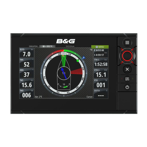
- Page 40 The indicator will fade from blue to green the closer you get to the exact angle Tide rate and relative direction Magnetic variation Bearing to current waypoint Rudder angle Current waypoint ID The SailSteer panel | Zeus2 Operator Manual...
-
Page 41: Selecting Data Fields For The Sailsteer Panel
Data showing time calculations will be indicated with an -S extention: DTW-S Sailing Distance to Waypoint TTW-S Sailing Time to Waypoint ETA-S Sailing Estimated Time of Arrival The SailSteer panel | Zeus2 Operator Manual... -
Page 42: The Time Plot Panel
The Wind Plot panel includes wind direction and wind speed. The graphics are configured vertically with the newest data being displayed at the top of the screen. Time and Wind plots | Zeus2 Operator Manual... -
Page 43: Safe Operation With The Autopilot
Refer to "Using the autopilot in an EVC system" on page 52. Autopilot indication on the pages Description Autopilot indication in Status bar Autopilot pop-up Autopilot tile in Instrument bar Autopilot | Zeus2 Operator Manual... - Page 44 Autopilot tile in Instrument bar You can elect to show the autopilot tile in the Instrument bar. If the autopilot pop-up is turned off you can turn it on by selecting the tile in the Instrument bar. Autopilot | Zeus2 Operator Manual...
-
Page 45: The Autopilot Panel
Automatic steering, keeping the vessel on a straight bearing NoDrift line by compensating for drift Dodging Returns to NoDrift mode after a heading change Navigation steering. Steers the vessel to a specific waypoint or through a route Autopilot | Zeus2 Operator Manual... -
Page 46: Standby Mode
When the vessel is turning in AUTO mode, an instant reset of the mode activates the heading capture function. This will automatically cancel the turn, and the vessel will continue on the heading read from the compass the very moment you re-activated the mode. Autopilot | Zeus2 Operator Manual... -
Page 47: Nodrift Mode
NAV mode. If you reject this request, you can start NAV mode from the autopilot mode menu. When NAV mode is initiated, the autopilot will automatically keep the vessel on the leg. Autopilot | Zeus2 Operator Manual... -
Page 48: Wind Mode
The set course to steer (CTS) and set wind angle are entered from the compass heading and the wind transducer at the moment the WIND mode is selected. From that point the autopilot will change the course to maintain the wind angle as the wind direction may change. Autopilot | Zeus2 Operator Manual... -
Page 49: Wind Nav Mode
In WIND Nav mode the autopilot steers the boat given both wind and position data. In this mode the autopilot calculates the initial course change needed to navigate towards the active waypoint, but the pilot will also utilize the current wind direction in the calculation. Autopilot | Zeus2 Operator Manual... -
Page 50: Turn Pattern Steering
Square-turn makes the boat automatically turn 90° after having travelled a defined leg distance. You can at any time during the turn change the main heading and the distance of the leg until the boat makes a new 90° turn. Autopilot | Zeus2 Operator Manual... - Page 51 STBY/AUTO key to You can take command from an inactive Zeus bring up the mode selection menu, and then confirming active mode. Autopilot | Zeus2 Operator Manual...
-
Page 52: Using The Autopilot In An Evc System
The lock function is not available on the Zeus unit which has autopilot control! If the Zeus unit is part of an AP24/AP28 system, the unit can be locked from the AP24/ AP28 control unit. Autopilot | Zeus2 Operator Manual... - Page 53 Layline steering is useful when navigating. Cross Track Error (XTE) from the navigator will keep the boat on the track line. If the XTE from the navigator exceeds 0.15 NM, the autopilot will calculate the layline and track towards the waypoint. Autopilot | Zeus2 Operator Manual...
- Page 54 This option displays an overview of all autopilot steering parameters, and you can adjust parameters if required. For more details, refer to the separate Zeus Installation manual. Installation Used for autopilot installation and commissioning. See the separate Zeus Installation manual. Autopilot | Zeus2 Operator Manual...
-
Page 55: The Radar Panel
You can overlay the Radar image on the Chart. This can help you to easily interpret the radar image by correlating the radar targets with charted objects. When the radar overlay is selected, basic radar operational functions are available from the Chart panel’s menu. Radar | Zeus2 Operator Manual... -
Page 56: Radar Operational Modes
If your unit has a MARK key, you can press this key to immediately save a waypoint. If the cursor is active the waypoint will be saved at the cursor position. If the cursor is not active the waypoint will be saved at your vessel's position. Radar | Zeus2 Operator Manual... -
Page 57: Adjusting The Radar Image
A high setting will reduce the interference from other radars. In order not to miss weak targets, the interference rejection should be set low when no interference exists. The radar interference rejection option is available from the menu. Radar | Zeus2 Operator Manual... -
Page 58: Advanced Radar Options
Radar orientation is indicated on the upper left corner of the radar panel as either HU (Heading UP), NU (North Up) or CU (Course up). Heading up Rotates the radar image to display the current heading directly up on the radar image. Radar | Zeus2 Operator Manual... -
Page 59: Ebl/Vrm Markers
When positioned, you can turn the EBL/VRM on/off by selecting the relevant markers on the data bar, or by deselecting the marker from the menu. Radar | Zeus2 Operator Manual... -
Page 60: Setting A Guard Zone Around Your Vessel
An alarm will be activated when a radar target breaches the guard zone limits. You can select if the alarm will be activated when the target enters or exits the zone. Sensitivity The guard zone sensitivity can be adjusted to eliminate alarms for small targets. Radar | Zeus2 Operator Manual... -
Page 61: Marpa Targets
Information for the 3 MARPA targets closest to the vessel is also displayed in the data bar. When a target is selected, detailed information for the target can be displayed from the menu. You can display information about all MARPA targets by using the Vessels option on the Home page. Radar | Zeus2 Operator Manual... -
Page 62: Recording Radar Data
A circle can be added around your vessel to present the danger zone. The radius of the the ring is the same as the closest point of approach as set in Dangerous Vessels dialog. See Radar | Zeus2 Operator Manual... - Page 63 "Defining dangerous vessels" on page 83. An alarm will trigger if a vessel is tracking into your safe zone. Installation The Installation option is used for radar installation, described in the separate Zeus Installation manual. Radar | Zeus2 Operator Manual...
-
Page 64: The Echosounder Image
Upper and Lower range A-Scope Temperature graph Zoom bars Range scale Depth line Bottom * Optional echosounder image items. Ú Note: You turn the optional echosounder images on/off individually. See "Echosounder settings panel" on page 69. Echosounder | Zeus2 Operator Manual... -
Page 65: Zooming An Echosounder Image
You can use the menu to re-position the start point and the end point as long as the measuring function is active. When you select Finish measuring or press the X key, the image will resume to normal scrolling. Echosounder | Zeus2 Operator Manual... -
Page 66: Viewing Sounder History
Conversely, if the gain is set too low weak echoes may not be displayed. Auto gain The Auto gain option will keep the sensitivity at a level that works well under most conditions. Echosounder | Zeus2 Operator Manual... -
Page 67: Advanced Echosounder Options
Optional logging format for SideScan data. This will only be shown when StructureScan data is available. This format does not log all channesl into onen file. The format is used for third part application support on PC (like SonarWiz) that needs access to the StructureScan data. Echosounder | Zeus2 Operator Manual... -
Page 68: Echosounder View Options
The A-scope is a display of real-time echoes as they appear on the panel. The strength of the actual echo is indicated by both width and color intensity. Zoom bars The zoom bars shows he range that is magnified on a split panel with zoom view. Echosounder | Zeus2 Operator Manual... -
Page 69: Echosounder Settings
If more than one channel was recorded in the selected echosounder file, you can select which channel to display. You exit the view function by selecting the X in the upper right corner. Echosounder | Zeus2 Operator Manual... - Page 70 Noise may cause the echosounder to search for unrealistic depths. By setting the search depth manually the system will only display echoes received from objects within the set depth range. Installation Used for echosounder installation and setup. See the separate Zeus Installation manual. Echosounder | Zeus2 Operator Manual...
-
Page 71: Structurescan
• turning the rotary knob (when the cursor not is active) • using the panel zoom icons • by pinching or spreading on the screen Zoom level is shown on the upper left side of the panel. StructureScan™ | Zeus2 Operator Manual... -
Page 72: Using The Cursor On The Structurescan™ Panel
Depending of the view selected, the scroll bar is on the far right side (DownScan) or at the bottom of the screen (SideScan). You can pan the image history by dragging up/down (SideScan) or left/right DownScan. To resume normal StructureScan scrolling, press Clear cursor. StructureScan™ | Zeus2 Operator Manual... -
Page 73: Setting Up The Structurescan Image
If required, the left/right SideScanning images can be flipped to match the corresponding side of you vessel. Range Lines Range lines can be added to the image to make it easier to estimate depth (Downscan) and distance (SideScan). StructureScan™ | Zeus2 Operator Manual... - Page 74 Recording StructureScan data You can record StructureScan data and save the file internally in the Zeus unit, or onto an SD card as described in "Recording echosounder data" on page 67. StructureScan™ | Zeus2 Operator Manual...
-
Page 75: Structuremap
Ú Note: Live mode does not save any data. If the unit is turned off, all recent data is lost. StructureMap | Zeus2 Operator Manual... -
Page 76: Structuremap Tips
Navionics, Insight and other third-party charting cards compatible with the Zeus systems. When using StructureMap with mapping cards, copy the StructureMap (.smf ) files to the unit’s internal memory. We recommend keeping copies of StructureMap files on external SD cards. StructureMap | Zeus2 Operator Manual... -
Page 77: Structure Options
Filters the signal interference and reduces the on-screen clutter Clear live history Clears existing live mode history trails from the screen and begins showing only the most current data Record data Records StructureScan data Source Selects StructureMap source StructureMap | Zeus2 Operator Manual... -
Page 78: Ais
Selected AIS target, activated The target will return to default target symbol by selecting a target symbol. when the cursor is removed from the symbol. | Zeus2 Operator Manual... -
Page 79: Viewing Information About Ais Targets
AIS information on radar panels The radar data bar includes information on up to 3 AIS targets. The targets are listed with the closest target on top, and are color coded to indicate target status. | Zeus2 Operator Manual... -
Page 80: Calling An Ais Vessel From The Zeus
If you ignore the alarm, the AIS SART icon remains visible on your chart, and the AIS SART remains in the Vessels list. If the AIS stops receiving the AIS SART message, the AIS SART remains in the Vessels list for 10 minutes after it receives the last signal. Save the waypoint | Zeus2 Operator Manual... -
Page 81: Vessel Alarms
The CPA and TCPA defines when a vessel is dangerous regardless of the enabled/disabled state. Vessel message Controls whether an alarm shall be activated when a message is received from an AIS target | Zeus2 Operator Manual... -
Page 82: Vessel Settings
For own vessel heading information is read from active heading sensor, and COG information is as received from the active GPS. For other vessels COG data is included in the message received from the AIS system. | Zeus2 Operator Manual... - Page 83 Different line style is used on the extension lines to indicate motion as shown below. AIS vessels shown with Absolute motion AIS vessels shown with Relative motion AIS icon orientation Sets the orientation of the AIS icon; either based on heading or COG information. | Zeus2 Operator Manual...
-
Page 84: Instrument Panels
Select the gauge you want to change. Selected gauge is indicated with a blue background Select information to be display, limits and eventually change the source for the information Save your changes by selecting the save option in the menu Instrument panels| Zeus2 Operator Manual... -
Page 85: Audio
Installation manual and the documentation included with the audio device. Enabling audio Compatible audio device connected to the NMEA 2000 network should automatically be . If not, enable the feature from the Advanced Settings dialog. identified by the Zeus Audio| Zeus2 Operator Manual... -
Page 86: The Audio Panel
Select to select frequency rewind/play fast previous/next Press and hold to tune in a channel forward track Select to select next/previous favourite channel Select to start Select to pause playback Select to display the volume slider Audio| Zeus2 Operator Manual... -
Page 87: Setting Up The Audio System
To use the AUX source for a different device, the Sirius must be detached from the AUX source. Ú Note: To use SiriusXM an optional SiriusXM tuner must be connected to the FUSION server. Audio| Zeus2 Operator Manual... -
Page 88: Operating The Audio System
You can lock selected Sirius channels from being broadcasted unless an unlock code is entered. When the function is activated, a 4 digit code must be entered before the locking is activated. The same code must be entered before a locked channel can be released. Audio| Zeus2 Operator Manual... -
Page 89: Weather
Wind speed: 35 knots Wind speed: 60 knots GRIB weather A GRIB file contains forecast information for a set number of days. It is possible to animate the weather data which shows how weather systems are developing. Weather| Zeus2 Operator Manual... - Page 90 From this menu you can also animate the weather forecast as described later in this chapter. Description Wind barbs Pressure contours GRIB information window Weather| Zeus2 Operator Manual...
-
Page 91: Siriusxm™ Weather
The ESN shows the electronic serial number for the WM-2 module. Sirius weather display The Sirius weather can be displayed as an overlay on your chart panel. When weather overlay is selected, the chart menu will increase to show the available weather options. Weather| Zeus2 Operator Manual... - Page 92 (red) - future (yellow) Hurricane (category 1-5) tracking; past (grey) - present (red) - future (yellow) Tropical disturbance/depression tracking; past (grey) - present (red) - future (yellow) Storm attributes Lightning Watch box location and warning Marine zone location Weather| Zeus2 Operator Manual...
- Page 93 • if the colored wave height overlay was turned on, you can animate the future (the predictions). When activated, the time for the current graphic animation will be displayed in the lower left corner of the chart panel. Weather| Zeus2 Operator Manual...
- Page 94 You can also get an alarm as a severe weather forecast alarm issued for your chosen marine zone. A watchbox is defined by the National Weather Service. When the alarm is turned on you will get an alarm when your vessel is inside or is entering into a watchbox. Weather| Zeus2 Operator Manual...
-
Page 95: Video
Adjusting the video image You can optimize the video display by adjusting the video image settings. The settings are adjusted individually for each video source. Default for all settings: 50%. Video| Zeus2 Operator Manual... -
Page 96: Flir Camera Control
In this mode the zoom is represented in levels (0, 2 and 4 times zoom). Each press on a zoom button will increment or decrement the zoom level. Optical zoom Available in daylight mode. In this mode the camera will zoom as long as you press a zoom panel button. Video| Zeus2 Operator Manual... - Page 97 Black = Hot and White = Cold The FLIR camera’s home position You can set the current pan and tilt position as the camera’s home position. You can later quickly return to this camera position. Video| Zeus2 Operator Manual...
-
Page 98: Alarms
If more than one alarm is activated simultaneously, the alarm message will display a list of up to 3 alarms. The alarms are listed in the order they occur with the alarm activated first at the top. The remaining alarms are available in the Alarms dialog Alarms| Zeus2 Operator Manual... -
Page 99: Acknowledging A Message
Alarms dialog All alarms are setup in the Alarms Settings dialog. The alarm dialogs can also be activated from the Tools panel. The alarm dialogs includes information about active alarms and alarm history. Alarms| Zeus2 Operator Manual... -
Page 100: Trip Calculator
Displays voyage and engine information, with reset option for all data fields. Today Displays voyage and engine information for current date. All data fields are automatically reset when the date changes. Files File management system for files, waypoints, routes, tracks and settings. Tools| Zeus2 Operator Manual... - Page 101 Find Search function for chart items. Tools| Zeus2 Operator Manual...
-
Page 102: Demo Mode
A set of source files is included in your system, and you can import files by using an SD card inserted into the unit’s card reader. You can also use your own recorded files in the simulator. Simulator| Zeus2 Operator Manual... -
Page 103: Advanced Simulator Settings
Otherwise, GPS data including speed and course comes from the selected source file. Set start position Moves the vessel to current cursor position. Ú Note: This option is only available when the GPS source is set to Simulated course. Sailing Opens dialog for selecting sail specific simulator data. Simulator| Zeus2 Operator Manual... -
Page 104: Preventive Maintenance
Checking the connectors The connectors should be checked by visual inspection only. Push the connector plugs into the connector, if the connector plugs are equipped with a lock; ensure that this is in the correct position. Maintenance| Zeus2 Operator Manual... -
Page 105: Software Upgrades
Once accepted the log file is written to the chosen location. Software upgrades The latest software for the Zeus will be available for download from our website; bandg.com. Detailed instructions for how to install the software will follow the upgrade files. Maintenance| Zeus2 Operator Manual... -
Page 106: Backing Up Your System Data
The graphics shows how to export waypoints, routes and tracks. Select the files option from the home page Select the data you want to export Select the export option in the dialog Select export format Select destination folder Enter name for exported file. Maintenance| Zeus2 Operator Manual... - Page 108 0980...
Need help?
Do you have a question about the Zeus2 and is the answer not in the manual?
Questions and answers
We have lost AP but have AP Rudder data missingwarning
If the AP Rudder data is missing for B&G part number 2, you should check the autopilot settings after a reset. A system reset can cause missing data such as AP Heading or Rudder data. Review and reconfigure the autopilot settings to restore proper function. Also, ensure that all sensors and data sources (e.g., compass, rudder sensor) are properly connected and working.
This answer is automatically generated