Table of Contents
Advertisement
Available languages
Available languages
B B
D D
M M
S S
1 1
0 0
0 0
1 1
0 0
" "
( (
2 2
5 5
4 4
M M
M M
) )
C C
O O
M M
P P
O O
U U
N N
D D
M M
I I
T T
E E
R R
S S
A A
W W
B B
D D
M M
S S
1 1
0 0
0 0
1 1
0 0
" "
( (
2 2
5 5
4 4
M M
M M
) )
C C
O O
M M
P P
O O
U U
N N
D D
M M
I I
T T
E E
R R
S S
A A
W W
INSTRUCTION MANUAL
BEFORE RETURNING THIS PRODUCT FOR ANY REASON
PLEASE CALL 1-800-HOW-TO (544-6986)
IF YOU SHOULD EXPERIENCE A PROBLEM WITH YOUR BLACK & DECKER PRODUCT,
CALL 1-800-54-HOW-TO (544-6986).
BEFORE YOU CALL, HAVE THE FOLLOWING INFORMATION AVAILABLE, CATALOG No.,
TYPE No., AND DATE CODE. IN MOST CASES, A BLACK & DECKER REPRESENTATIVE
CAN RESOLVE THE PROBLEM OVER THE PHONE. IF YOU HAVE A SUGGESTION OR COMMENT,
GIVE US A CALL.YOUR FEEDBACK IS VITAL TO BLACK & DECKER.
SAVE THIS MANUAL FOR FUTURE REFERENCE.
VEA EL ESPAÑOL EN LA CONTRAPORTADA.
POUR LE FRANÇAIS, VOIR LA COUVERTURE ARRIÈRE.
INSTRUCTIVO DE OPERACIÓN, CENTROS DE SERVICIO Y
PÓLIZA DE GARANTÍA. ADVERTENCIA: LÉASE ESTE
INSTRUCTIVO ANTES DE USAR EL PRODUCTO.
Advertisement
Chapters
Table of Contents

Related Manuals for Black & Decker BDMS100


Summary of Contents for Black & Decker BDMS100
-
Page 1: Instruction Manual
” ” ” ” INSTRUCTION MANUAL BEFORE RETURNING THIS PRODUCT FOR ANY REASON PLEASE CALL 1-800-HOW-TO (544-6986) IF YOU SHOULD EXPERIENCE A PROBLEM WITH YOUR BLACK & DECKER PRODUCT, CALL 1-800-54-HOW-TO (544-6986). BEFORE YOU CALL, HAVE THE FOLLOWING INFORMATION AVAILABLE, CATALOG No., TYPE No., AND DATE CODE. -
Page 2: Table Of Contents
TABLE OF CONTENTS IMPORTANT SAFETY INSTRUCTIONS ............2 SAFETY GUIDELINES . -
Page 3: Safety Guidelines
SAFETY GUIDELINES - DEFINITIONS It is important for you to read and understand this manual. The information it contains relates to protecting YOUR SAFETY and PREVENTING PROBLEMS. The symbols below are used to help you recognize this information. Indicates an imminently hazardous situation which, if not avoided, will result in death or serious injury. Indicates a potentially hazardous situation which, if not avoided, could result in death or serious injury. -
Page 4: General Safety Rules
GENERAL SAFETY RULES READ AND UNDERSTAND ALL WARNINGS AND OPERATING INSTRUCTIONS BEFORE USING THIS EQUIPMENT. Failure to follow all instructions listed below, may result in electric shock, fire, and/or serious personal injury or property damage. IMPORTANT SAFETY INSTRUCTIONS machine or an attachment to do a job for which it FOR YOUR OWN SAFETY, READ THE was not designed. -
Page 5: Additional Specific Safety Rules
ADDITIONAL SPECIFIC SAFETY RULES FAILURE TO FOLLOW THESE RULES MAY RESULT IN SERIOUS PERSONAL INJURY. If the slide mechanism is not locked, the saw can kick DO NOT OPERATE THIS MACHINE until it is back toward you. completely assembled and installed according to the ALLOW THE MOTOR TO COME TO FULL SPEED instructions. -
Page 6: Power Connections
POWER CONNECTIONS A separate electrical circuit should be used for your machines. This circuit should not be less than #12 wire and should be protected with a 20 Amp time lag fuse. If an extension cord is used, use only 3-wire extension cords which have 3- prong grounding type plugs and matching receptacle which will accept the machine’s plug. -
Page 7: Carton Contents
CARTON CONTENTS Fig. 1 Fig. 2 Remove the miter saw and all loose items from the carton. Do not lift the miter saw by the switch handle. This action can cause misalignment. Always lift the machine by the base or the carrying handle. Miter Saw Dust Bag 1/2"... -
Page 8: Extension Cords
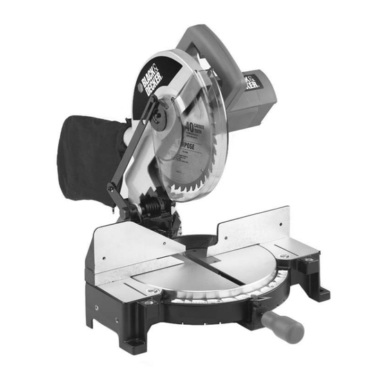
FOREWORD Model BDMS100 is a 10" Compound Power Miter Saw designed to cut wood, plastic, and aluminum. Compound angle and bevel cutting are easy and accurate. It can crosscut up to 5-3/4" x 2-3/8", miter at 45° both left and right up to 4- 1/8"... -
Page 9: Assembly
For your own safety, do not connect the machine to the power source until the machine is completely assembled and you read and understand the entire instruction manual. Thread the table lock handle (A) Fig. 4 into the threaded hole (B) of the arm bracket. -
Page 10: Moving Cuttinghead To The Up Position
Rotate the table to the left until the index stop engages with the 90° positive stop (Fig. 6). Tighten the table lock handle (A). Fig. 6 MOVING CUTTINGHEAD TO THE UP POSITION Push down on handle (A), Inset, Fig. 7. Pull out the cuttinghead lock knob (B). Move the cuttinghead (C) to the up position (Fig. -
Page 11: Operation
OPERATION OPERATIONAL CONTROLS AND ADJUSTMENTS TABLE HAZARD AREA The area inside the two red lines (A) Fig. 11 on the table is designated as a hazard zone. Never place your hands inside this area while the machine is running. Fig. 11 STARTING AND STOPPING THE MITER SAW To start the miter saw, depress the switch trigger (A) Fig. -
Page 12: Pointer And Scale
ROTATING THE TABLE FOR MITER CUTTING Your miter saw will cut any angle from a straight 90° cut to 47° right and left. Turn the lock handle (A) Fig. 13 counter-clockwise one or two turns, depress the index lever (B), and move the control arm to the desired angle. Tighten the lock handle (A). The miter saw is equipped with positive stops at the 0°, 22.5°, 31.62°, and 45°... -
Page 13: Tilting Cuttinghead For Bevel Cutting
TILTING THE CUTTINGHEAD FOR BEVEL CUTTING You can tilt the cuttinghead of your compound miter saw to cut any bevel angle from a 90° straight cut off to a 45° left bevel angle. Loosen the bevel lock handle (A) Fig. 18, tilt the cutting arm (B) to the desired angle, and tighten the lock handle (A). -
Page 14: Fence Adjustment
FENCE ADJUSTMENT DISCONNECT MACHINE FROM POWER SOURCE! In order that the saw can bevel to a full 47 degrees left, the left side of the fence can be adjusted to the left to provide clearance. To adjust the fence, loosen the plastic knob shown in Figure 22 and slide the fence to the left. Make a dry run with the saw turned off and check for clearance. -
Page 15: Adjusting 90/45 Bevel Stops
ADJUSTING 90° AND 45° BEVEL STOPS DISCONNECT MACHINE FROM POWER SOURCE! Loosen the bevel lock handle (A) Fig. 18 and move the cutting arm (B) Fig. 18 all the way to the right. Tighten the bevel lock handle. Place one end of a square (A) Fig. 24 on the table and the other end against the blade. Check to see if the blade is 90° to the table (Fig. -
Page 16: Typical Operations And Helpful Hints
ADJUSTING THE TENSION OF THE CUTTINGHEAD RETURN SPRING DISCONNECT MACHINE FROM POWER SOURCE! The tension of the cuttinghead return spring was adjusted at the factory so that the cuttinghead returns to the "up" position after cutting. To adjust the spring tension, loosen the locknut (A) Fig. 29 and turn the screw (B) (clockwise to increase or counterclockwise to decrease the spring tension). -
Page 17: General Cutting Operations
GENERAL CUTTING OPERATIONS Your machine has the capacity to cut standard 2 x 4’s, lying flat or on edge, at the 45° right and left miter angles (Fig. A1 & A2). A standard 2 x 6 can be cut in the 90° straight cut-off position in one pass (Fig. A3). Cutting a standard 4 x 4 can be accomplished with one pass (Fig. -
Page 18: Cutting Aluminum
CUTTING ALUMINUM Aluminum extrusions such as used for making aluminum screens and storm windows can easily be cut with your compound miter saw. When cutting aluminum extrusions, or other sections that can be cut with a saw blade and are within the capacity of the machine, position the material so the blade is cutting through the smallest cross-section (Fig. -
Page 19: Cutting Crown Moulding
CUTTING CROWN MOULDING One of the many features of the saw is the ease of cutting crown moulding. The following is an example of cutting both inside and outside corners on 52°/38° wall angle crown moulding. 1. Move the table to the 31.62° right miter position and lock the table in position. NOTE: A positive stop is provided to find this angle quickly. -
Page 20: Maintenance
MAINTENANCE CHANGING THE BLADE Use only cross-cutting saw blades. When using carbide-tipped blades, do not use blades with deep gullets as they can deflect and contact the guard. Use only 10" diameter saw blades which are rated for 5200 rpm or higher and have 5/8" diameter arbor holes. -
Page 21: Brush Inspection And Replacement
BRUSH INSPECTION AND REPLACEMENT Brush life varies. It depends on the load on the motor. Check the brushes after the first 50 hours of use for a new machine or after a new set of brushes has been installed. After the first check, examine them after about 10 hours of use until a replacement is necessary. -
Page 22: Service Information
TROUBLESHOOTING BE SURE TO FOLLOW SAFETY RULES AND INSTRUCTIONS TROUBLE! SAW WILL NOT START WHAT’S WRONG? WHAT TO DO… 1.Saw not plugged in. 1.Plug in saw. 2.Fuse blown or circuit breaker tripped. 2.Replace fuse or reset circuit breaker. 3.Cord damaged. 3.Have cord replaced by authorized service center. - Page 23 À À À À MODE D’EMPLOI AVANT DE RETOURNER CE PRODUIT POUR QUELQUE RAISON QUI SOIT, VEUILLEZ APPELER AU 1-800-54-HOW-TO (544-6986) CONSERVER CE MODE D’EMPLOI POUR UN USAGE ULTÉRIEUR.
-
Page 24: Directives De Sécurité Importantes
TABLE DES MATIÈRES DIRECTIVES DE SÉCURITÉ IMPORTANTES ........... . .24 LIGNES DIRECTRICES EN MATIÈRE DE SÉCURITÉ... -
Page 25: Lignes Directrices En Matière De Sécurité
LIGNES DIRECTRICES EN MATIÈRE DE SÉCURITÉ - DÉFINITIONS Il est important que vous lisiez et compreniez ce mode d’emploi. Les informations qu’il contient concernent VOTRE SÉCURITÉ et visent à ÉVITER TOUT PROBLÈME. Les symboles ci-dessous servent à vous aider à reconnaître cette information. indique une situation dangereuse imminente qui, si elle n’est pas évitée, causera la mort ou des graves blessures. -
Page 26: Règles Générales De Sécurité
RÈGLES GÉNÉRALES DE SÉCURITÉ LIRE ATTENTIVEMENT TOUTES LES MISES EN GARDE ET DIRECTIVES D’UTILISATION AVANT D'UTILISER CET ÉQUIPEMENT. À défaut de suivre les directives sous-mentionnées, un choc électrique, un incendie, des dommages ou une blessure corporelle grave pourraient survenir. DIRECTIVES DE SÉCURITÉ IMPORTANTES 1. -
Page 27: Règles De Sécurité Spécifiques Supplémentaires
RÈGLES DE SÉCURITÉ SPÉCIFIQUES SUPPLÉMENTAIRES NÉGLIGER DE SUIVRE CES RÈGLES RISQUE D’ENTRAÎNER DES BLESSURES CORPORELLES GRAVES. SI NO SE SIGUEN ESTAS NORMAS, EL RESULTADO PODRÍA SER LESIONES PERSONALES GRAVES. la scie peut se retourner et vous percuter. NE FAITES PAS FONCTIONNER CETTE MACHINE avant LAISSER LE MOTEUR atteindre son plein régime avant qu’elle ne soit entièrement assemblée et installée de commencer la coupe. - Page 28 CONNEXIONS ÉLECTRIQUES Un circuit électrique séparé doit être utilisé pour vos machines. Ce circuit doit utiliser un câble de calibre 12 au minimum et doit être protégé par un fusible temporisé de 20 A. Si vous utilisez une rallonge électrique, n’utilisez que des rallonges à...
-
Page 29: Contenu Du Carton
CONTENU DU CARTON Fig. 1 Fig. 2 Retirer du carton la scie à onglets ainsi que toutes les pièces. Ne pas soulever la scie à onglets par la poignée de la gâchette. Ceci pourrait provoquer un mauvais alignement. Toujours soulever la machine par la base de la poignée de transport. Scie à... -
Page 30: Description Fonctionnelle
AVANT-PROPOS Le modèle BDMS100 est une scie électrique à onglets mixtes de 254 mm (10 po) destinée à couper le bois, le plastique et l’aluminium. Les coupes en biseau et à angles mixtes sont faciles et précises. Cet outil peut effectuer des coupes transversales mesurant jusqu’à... -
Page 31: Assemblage
Pour votre propre sécurité, ne pas brancher la machine à une source d’alimentation jusqu’à ce que la machine soit entièrement assemblée, ni avant d'avoir lu et compris l’intégralité de ce mode d'emploi. FIXATION DE LA POIGNÉE DE BLOCAGE DE LA TABLE Visser la poignée de blocage de la table (A, Fig. - Page 32 Tourner la table vers la gauche jusqu’à ce que la butée soit complètement enfoncée dans la butée fixe à 90° (Fig. 6). Serrer fermement la poignée de blocage de la table (A). Fig. 6 METTRE LA FRAISE ROTATIVE EN POSITION HAUTE Pousser la poignée vers le bas (A) (encart, Fig.
-
Page 33: Fonctionnement
FONCTIONNEMENT COMMANDES ET RÉGLAGES OPÉRATIONNELS ZONE A RISQUE DE LA TABLE La zone comprise entre les deux lignes rouges (A, Fig. 11) sur la table est considérée comme zone à risque. Ne jamais placer les mains à l’intérieur de cette zone lorsque la machine est en marche. - Page 34 TOURNER LA TABLE POUR EFFECTUER UNE COUPE A ONGLET La scie à onglets peut couper selon n’importe quel angle compris entre un angle droit à 90° et un angle de 47° à droite comme à gauche. Tourner la poignée de blocage (A, Fig. 13) dans le sens inverse des aiguilles d’une montre sur un ou deux tours, enfoncer le levier (B), puis positionner l'arbre de contrôle selon l’angle désiré.
- Page 35 INCLINER LA FRAISE ROTATIVE POUR EFFECTUER UNE COUPE EN BISEAU Il est possible d'incliner la fraise rotative de la scie à onglets mixtes pour effectuer une coupe en biseau allant d’un angle droit de 90° jusqu'à un angle de biseau gauche à 45°. Desserrer la poignée de blocage de biseau (A, Fig.
- Page 36 RÉGLAGE DU GUIDE DÉBRANCHER LA MACHINE DE LA SOURCE D’ALIMENTATION! Afin que la scie puisse biseauter à 47 degrés vers la gauche, le côté gauche du guide peut être ajusté afin de fournir le dégagement suffisant. Pour régler le guide, desserrer la poignée en plastique comme indiqué sur la Fig. 22, puis faire glisser le guide vers la gauche.
- Page 37 RÉGLAGE DES BUTÉES DE BISEAU À 90° ET 45° DEBRANCHER LA MACHINE DE LA SOURCE D’ALIMENTATION! Desserrer la poignée de blocage de biseau (A, Fig. 18) et déplacer complètement le bras de coupe (B, Fig. 18) vers la droite. Serrer fermement la poignée de blocage de biseau. Placer un côté...
- Page 38 RÉGLAGE DE LA TENSION DU RESSORT DE RAPPEL DE LA FRAISE ROTATIVE DÉBRANCHER LA MACHINE DE LA SOURCE D’ALIMENTATION! La tension du ressort de rappel de la fraise rotative a été réglée à l’usine de façon à ce que la fraise rotative se remette en position «...
- Page 39 OPÉRATIONS DE COUPE GÉNÉRALES Votre machine a la capacité d'effectuer des coupes standard de 2 x 4, à plat ou sur les bords, à angle de biseau gauche et droit à 45° (Fig. A1 et A2). Une coupe standard de 2 x 6 peut être effectuée à angle droit de 90° en un passage (Fig. A3). Une coupe standard de 4 x 4 peut être accomplie en un passage (Fig.
- Page 40 COUPER DE L’ALUMINIUM La scie à onglets mixtes permet de couper facilement les extrusions d’aluminium telles que celles utilisées pour fabriquer des écrans et des contre-fenêtres en aluminium. Pour couper des extrusions d’aluminium, ou autres sections pouvant être coupées à l’aide d’une lame de scie et en particulier de cet outil, positionner le matériau de façon à...
- Page 41 COUPE DE MOULURES COURONNÉES Les nombreuses fonctionnalités de la scie incluent la coupe facile de moulures couronnées. L’exemple suivant concerne une coupe e coins internes et externes sur des moulures couronnées qui forment un angle de 52°/38° avec le mur. 1.
-
Page 42: Entretien
ENTRETIEN CHANGEMENT DE LA LAME Utiliser uniquement des lames de scie à tronçonner. Avec l'utilisation de lames à pointe carburée, ne pas utiliser de lames à dents très espacées car elles peuvent entrer en contact avec le pare-main et le faire dévier. Utiliser uniquement des lames de scie de diamètre 10 po (254 mm) conçues Fig. - Page 43 INSPECTION ET REMPLACEMENT DE LA BROSSE La durée de vie de la brosse est variable. Elle dépend de la charge du moteur. Vérifier les brosses après les 50 premières heures d’utilisation de la machine, ou après 50 heures d’utilisation de nouvelles brosses. Une fois la première vérification effectuée, examiner les brosses après environ 10 heures d'utilisation, et ce jusqu’à...
-
Page 44: Réparation
DÉPANNAGE SUIVRE LES RÈGLES ET CONSIGNES DE SÉCURITÉ PROBLÈME! LA SCIE NE DÉMARRE PAS QUEL EST LE PROBLÈME ? QUE FAIRE… 1.Scie non branchée. 1.Brancher la scie. 2.Fusible grillé ou disjoncteur déclenché.2.Remplacer le fusible ou réinitialiser le disjoncteur. 3.Cordon endommagé. 3.Faire remplacer le cordon par un centre de réparation agréé. - Page 45 ” ” ” ” MANUAL DE INSTRUCCIONES ANTES DE DEVOLVER ESTE PRODUCTO POR CUALQUIER RAZÓN, POR FAVOR LLAME AL (55)5326-7100 CONSERVE ESTE MANUAL PARA FUTURAS CONSULTAS.
- Page 46 ÍNDICE INSTRUCCIONES IMPORTANTES SOBRE SEGURIDAD ......... . .46 NORMAS DE SEGURIDAD .
- Page 47 NORMAS DE SEGURIDAD - DEFINICIONES Es importante que lea y comprenda este manual. La información que contiene se relaciona con la protección de SU SEGURIDAD y la PREVENCIÓN DE PROBLEMAS. Los símbolos que siguen se utilizan para ayudarlo a reconocer esta información.
-
Page 48: Instrucciones Importantes Sobre Seguridad
NORMAS GENERALES DE SEGURIDAD LEA Y COMPRENDA TODAS LAS ADVERTENCIAS Y LAS INSTRUCCIONES DE OPERACIÓN ANTES DE UTILIZAR ESTE EQUIPO. El incumplimiento de cualquiera de las instrucciones enumeradas abajo puede provocar descarga eléctrica, incendio o lesiones personales graves o daños a la propiedad. INSTRUCCIONES IMPORTANTES SOBRE SEGURIDAD POR SU PROPIA SEGURIDAD, LEA EL MANUAL UTILICE LA MÁQUINA ADECUADA. -
Page 49: Normas De Seguridad Específicas Adicionales
NORMAS DE SEGURIDAD ESPECÍFICAS ADICIONALES LA FALTA DE CUMPLIMIENTO DE ESTAS NORMAS PUEDE PROVOCAR LESIONES PERSONALES GRAVES. HAGA FUNCIONAR EL MOTOR a toda velocidad antes NO OPERE ESTA MÁQUINA HASTA que no esté armada de comenzar a cortar. Comenzar a cortar demasiado e instalada completamente, según las instrucciones. - Page 50 CONEXIONES ELÉCTRICAS Debe utilizar un circuito eléctrico independiente para sus máquinas. Este circuito no debe ser menor a un cable Nº 12 y debe estar protegido con un fusible de acción retardada de 20 amperios. Si utiliza un cable prolongador, debe ser únicamente los de 3 conductores, que tengan enchufes a tierra de 3 patas y receptáculos correspondientes que acepten el enchufe de la máquina.
-
Page 51: Contenido De La Caja
CONTENIDO DE LA CAJA Fig. 1 Fig. 2 Retire la sierra ingletadora y todos los elementos sueltos de la caja. No tome la sierra ingletadora por el mango del interruptor para levantarla. Esto puede afectar su alineación. Siempre levante la máquina tomándola por la base o el mango de transporte. Sierra ingletadora Bolsa recolectora de polvo Llave para cambio de hoja de 12,7 mm (1/2”) -
Page 52: Descripción De Las Funciones
DESCRIPCIÓN DE LAS FUNCIONES INTRODUCCIÓN El modelo BDMS100 es una Sierra ingletadora eléctrica compuesta de 254 mm (10”) diseñada para cortar madera, plástico y aluminio. Los cortes biselados y en ángulo compuestos son fáciles de realizar y precisos. Puede cortar transversalmente hasta 146 x 60,3 mm (5-3/4”... - Page 53 Por su propia seguridad, no conecte la máquina a la fuente de alimentación hasta que esté armada completamente, y haya leído y comprenda todo el manual de instrucciones. COLOCACIÓN DEL INDICADOR DE BISEL DESCONECTE LA MÁQUINA DE LA FUENTE DE ALIMENTACIÓN. Afloje el mango de bloqueo de bisel (K), Figura 3, e incline el brazo de la sierra ingletadora hasta la posición de 45 grados.
- Page 54 Rote la mesa hacia la izquierda hasta que el tope del indicador se trabe en el tope positivo de 90º (Figura 6). Ajuste el mango de bloqueo de la mesa (A). Fig. 6 PUESTA DEL CABEZAL DE CORTE EN LA POSICIÓN SUPERIOR Empuje el mango hacia abajo (A), Recuadro, Figura 7.
-
Page 55: Operación
OPERACIÓN CONTROLES DE OPERACIÓN Y AJUSTES ÁREA DE PELIGRO EN LA MESA El área comprendida entre las dos líneas rojas (A), Figura 11, en la mesa, es considerada una zona de peligro. Nunca coloque las manos dentro de esta área mientras la máquina esté funcionando. Fig. - Page 56 ROTACIÓN DE LA MESA PARA EL CORTE DE INGLETE La sierra ingletadora cortará cualquier ángulo desde un corte recto de 90º hasta 47º a la derecha o a la izquierda. Gire el mango de bloqueo (A), Figura 13, en el sentido inverso a las agujas del reloj, una o dos vueltas, presione la palanca del indicador (B) y mueva el brazo de control hasta el ángulo deseado.
- Page 57 INCLINACIÓN DEL CABEZAL DE CORTE PARA EL CORTE BISELADO Usted puede inclinar el cabezal de corte de la sierra ingletadora compuesta para cortar cualquier ángulo de bisel, desde un corte recto de 90º hasta un ángulo de bisel izquierdo de 45º. Afloje el mango de bloqueo de bisel (A), Figura 18, incline el brazo de corte (B) hasta el ángulo deseado y vuelva a ajustar el mango de bloqueo (A).
- Page 58 REGULACIÓN DE LA GUÍA DESCONECTE LA MÁQUINA DE LA FUENTE DE ALIMENTACIÓN. Para que la sierra pueda biselar a 47 grados completos a la izquierda, se puede regular el lado izquierdo de la guía hacia la izquierda para proporcionar espacio. Para ajustar la guía, afloje la perilla de plástico que se muestra en la Figura 22, y deslice la guía hacia la izquierda.
- Page 59 AJUSTE DE LOS TOPES DE BISEL A 90º Y 45º DESCONECTE LA MÁQUINA DE LA FUENTE DE ALIMENTACIÓN. Afloje el mango de bloqueo de bisel (A), Figura 18, y mueva el brazo de corte (B), Figura 18, completamente hacia la derecha. Ajuste el mango de bloqueo de bisel.
- Page 60 REGULACIÓN DE LA TENSIÓN DEL RESORTE DE RETORNO DEL CABEZAL DE CORTE DESCONECTE LA MÁQUINA DE LA FUENTE DE ALIMENTACIÓN. La tensión del resorte de retorno del cabezal de corte viene ajustada de fábrica, de modo que el cabezal de corte regresa a la posición “superior”...
- Page 61 OPERACIONES GENERALES DE CORTE La máquina tiene la capacidad de cortar 2 x 4 estándar, en posición plana o de canto, en los ángulos de inglete derecho e izquierdo a 45º (Figuras A1 y A2). Un 2 x 6 estándar se puede cortar en la posición de corte derecho a 90º con una sola pasada (Figura A3). Se puede lograr un corte de un 4 x 4 estándar con una sola pasada (Figura A4).
- Page 62 CORTE DE ALUMINIO Las extrusiones de aluminio, tales como las utilizadas para realizar pantallas de aluminio y ventanas de tormenta, se pueden cortar fácilmente con la sierra ingletadora compuesta. Para cortar extrusiones de aluminio, u otras secciones que se pueden cortar con la hoja de la sierra y están dentro de las posibilidades de la máquina, busque una posición para colocar el material donde se pueda cortar de través por la parte más pequeña (Figura 31).
- Page 63 CORTE DE MOLDURAS DE CORONA Una de las tantas características de la sierra es la facilidad para cortar molduras de corona. El siguiente es un ejemplo de corte de la esquina interior y la exterior en una moldura de corona con un ángulo de pared de 52º/38º. 1.
-
Page 64: Cambio De La Hoja
MANTENIMIENTO CAMBIO DE LA HOJA Utilice hojas de sierra para corte transversal. Cuando utilice hojas con punta de carburo, no elija hojas con pasos profundos debido a que pueden entrar en contacto con la guarda y desviarla. Use únicamente hojas de sierra con un diámetro de 254 mm (10”), calificadas para 5.200 rpm o mayor y con orificios de Fig. - Page 65 INSPECCIÓN Y REEMPLAZO DE CEPILLOS La vida útil de los cepillos es variable. Dependerá de la carga en el motor. Controle los cepillos después de las primeras 50 horas de uso en una máquina nueva o luego de que se ha instalado un juego de cepillos nuevos. Después del primer control, examínelos cada 10 horas de uso aproximadamente, hasta que sea necesario un reemplazo.
-
Page 66: Detección De Problemas
DETECCIÓN DE PROBLEMAS ASEGÚRESE DE SEGUIR LAS REGLAS E INSTRUCCIONES DE SEGURIDAD PROBLEMA: LA SIERRA NO ENCIENDE ¿QUÉ SUCEDE? QUÉ HACER… 1.La sierra no está enchufada. 1.Enchufe la sierra. 2.Fusible quemado o interruptor 2.Reemplace el fusible o reinicie el automático activado. interruptor automático. - Page 67 BOSQUES DE CIDROS ACCESO RADIATAS NO. 42 eléctricas (Tools-Electric)” COL. BOSQUES DE LAS LOMAS. – Páginas amarillas – 05120 MÉXICO, D.F para Servicio y ventas TEL. 55-5326-7100 Cat.No. BDMS100 Form No. 488893-00 JULY ‘05-1 Copyright 2005 Black & Decker Printed in China ©...
Need help?
Do you have a question about the BDMS100 and is the answer not in the manual?
Questions and answers