Table of Contents
Advertisement
Quick Links
Download this manual
See also:
Installation Manual
Advertisement
Table of Contents

Related Manuals for Bosch UHI-SBG-0


Summary of Contents for Bosch UHI-SBG-0
- Page 1 UHI-SBG-0 Indoor Housing Installation Manual...
-
Page 3: Important Safeguards
This will prevent damage to the unit due to lightning and power line surges. 9. Safety Check - Upon completion of servicing or repairs to the unit, ask the service technician to perform safety checks to ensure proper operating condition. Bosch Security Systems, Inc. September 15, 2006 | F01U032279_01... -
Page 4: Safety Precautions
September 15, 2006 | F01U032279_01 Bosch Security Systems, Inc. - Page 5 UHI-SBG-0 Series Preface This guide describes how to install the UHI-SBG-0 Series. Audience This guide is intended for qualified installation and service personnel who are familiar with the applicable national and local electrical codes. Document Conventions Convention Meaning Bold Denotes a part, item, or assembly.
-
Page 6: Customer Support And Service
For additional information, see www.boschsecurity.com Related Publications Refer to the latest Bosch Security Systems, Inc. Databook for the most up-to-date datasheets. To obtain a copy of the Databook, please contact your local Bosch representative. You can also visit the Bosch Security Systems World Wide Web site at: http://www.boschsecurity.com to view a cur- rent listings of our publications. -
Page 7: Table Of Contents
NPT Fittings..........................5 Wire Preparation ........................7 Attaching the Camera and Spacer to the Tray ...............8 Mounting the Housing ......................9 Installing the Camera Tray ....................10 Connecting the Wires......................10 Operation..........................10 Maintenance ........................10 Bosch Security Systems, Inc. Installation Manual September 15, 2006 | F01U032279_01... - Page 8 UHI-SBG-0 Series September 15, 2006 | F01U032279_01 Installation Manual Bosch Security Systems, Inc.
-
Page 9: Parts List
Verify that all the parts listed in the Parts List below are included. If any items are missing, notify your Bosch Security Systems Sales or Customer Service Representative. The original packing carton is the safest container in which to transport the unit and must be used if returning the unit for service. -
Page 10: Exploded View
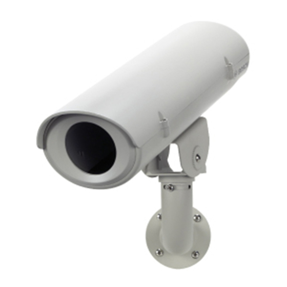
Exploded View UHI-SBG-0 Series Exploded View Reference Part Top cover Camera tray Connector block Plugs Front window holder NPT fittings Adjustable head Mount head J-mount base September 15, 2006 | F01U032279_01 Installation Manual Bosch Security Systems, Inc. - Page 11 Description Description The UHI-SBG-0 Series is an indoor housing which meets customer demand for appearance, cost competitiveness, and easy installation. Removal of two tamper-resistant screws is all that is necessary to open the cover and access the camera and lens in its mounted position. Power and video cabling can be routed through liquid tight fittings in the rear or bottom of the hous- ing.
-
Page 12: Cable Requirements
Cable Requirements UHI-SBG-0 Series Cable Requirements The specifications for the UHI-SBG-0 Series may vary depending on the model that you are operating. Refer to the following tables for more information. Video Transmission (coaxial) Type Specification Cable Type RG-59/U for runs < 300 m (1000 ft) RG-11/U for runs <... -
Page 13: Installing The Housing
NPT fittings (see Section 5.3: NPT Fittings). NPT Fittings The NPT fittings ensure a tight seal. Depending on how the UHI-SBG-0 is mounted, the NPT fit- tings can be installed either in the rear or from the bottom of the housing. The supplied 3/8 in. - Page 14 Sealants that release acetic acid may harm camera electronics. Use of drip loops is recommended on the wiring outside of the rear end cap. September 15, 2006 | F01U032279_01 Installation Manual Bosch Security Systems, Inc.
-
Page 15: Wire Preparation
Installing the Housing Wire Preparation Supply the UHI-SBG-0 with power by using a power cord that complies with the Nec 400-4 CEC rule 4-010 and is marked with INDOOR, W or W-A. For 24 V cameras, use the recom- mended maximum cable length chart for selecting the proper wire size. -
Page 16: Attaching The Camera And Spacer To The Tray
Attaching the Camera and Spacer to the Tray The UHI-SBG-0 includes two (2) spacers which may be required to keep the camera level (see Figure 5.7 on page 8). If a spacer is not used, the camera may dip down creating a port hole effect. -
Page 17: Mounting The Housing
Prepare the surface for mounting and install the J-mount. Fig. 6.3 Mounting the J-mount and Housing Place the UHI-SBG-0 housing on top of the J-mount while feeding the wires through the bottom or rear NPT fittings. Make sure that the weight of the camera is distributed evenly. -
Page 18: Installing The Camera Tray
Regularly scheduled maintenance will help prolong the operation life of this unit. Clean the viewing window as needed with a mild, nonabrasive detergent in water and a soft cloth. September 15, 2006 | F01U032279_01 Installation Manual Bosch Security Systems, Inc. - Page 19 Singapore 577180 The Netherlands Phone +65 6319 3450 Phone +1 800 289 0096 Phone +31 (0) 40 27 83955 +65 63139 3499 +1 585 223 9180 +31 (0) 40 27 86668 www.boschsecurity.com www.boschsecurity.us www.boschsecurity.com © Bosch Security Systems, Inc. 2006...
Need help?
Do you have a question about the UHI-SBG-0 and is the answer not in the manual?
Questions and answers