Table of Contents
Advertisement
Quick Links
Advertisement
Table of Contents

Related Manuals for Bosch UPH-C495N-L8120


Summary of Contents for Bosch UPH-C495N-L8120
- Page 1 High-speed Positioning System UPH Series Installation Manual...
-
Page 2: Table Of Contents
Fitting the Spotlight on the Bracket 5.4.4 Infrared LED Spotlight Connections and Configurations Configuring the Device Factory Use Only Protocol Setting the Address RS485 Line Termination Biphase/Bilinx Termination Connections Bosch Security Systems, Inc. Installation Manual Table of Contents | en F.01U.164.491 | 2.0 | 2010.03... - Page 3 8.4.1 Lens Modules Parameters and Area Masking 8.4.2 Infrared Parameters 8.4.3 Illuminator/Dinion Configuration Load Default Configuration Setup Info Menu Keyboard Commands List - Bosch Keyboard Commands List - Pelco Changing the Settings Changing the Numeric Fields Maintenance 10.1 Cleaning 10.2...
-
Page 4: Safety
Overloading - Do not overload outlets and extension cords. This can cause fire or electrical shock. Bosch Security Systems, Inc. Installation Manual Safety | en F.01U.164.491 | 2.0 | 2010.03... - Page 5 12. Servicing - Do not attempt to service this unit yourself. Opening or removing covers may expose you to dangerous voltage or other hazards. Refer all servicing to qualified service personnel. F.01U.164.491 | 2.0 | 2010.03 Installation Manual High-speed Positioning System Bosch Security Systems, Inc.
- Page 6 17. Attachments, changes or modifications - Only use attachments/accessories specified by the manufacturer. Any change or modification of the equipment, not expressly approved by Bosch, could void the warranty or, in the case of an authorization agreement, authority to operate the equipment.
-
Page 7: Important Notices
Disposal - Your Bosch product was developed and manufactured with high-quality material and components that can be recycled and reused. This symbol means that electronic and electrical appliances, which have reached the end of their working life, must be collected and disposed of separately from household waste material. - Page 8 SELV circuits. Because the ISDN circuits are treated like telephone-network voltage, avoid connecting the SELV circuit to the Telephone Network Voltage (TNV) circuits. Bosch Security Systems, Inc. Installation Manual Safety | en F.01U.164.491 | 2.0 | 2010.03...
- Page 9 Connecting System ground to Safety ground may result in ground loops that can disrupt the CCTV system. Video loss - Video loss is inherent to digital video recording; therefore, Bosch Security Systems cannot be held liable for any damage that results from missing video information. To minimize the risk of lost digital information, Bosch Security Systems recommends multiple, redundant recording systems, and a procedure to back up all analog and digital information.
-
Page 10: Fcc & Ices Compliance
Interference Problems (Comment identifier et résoudre les problèmes d’interférences de radio et de télévision). Cette brochure est disponible auprès du U.S. Government Printing Office, Washington, DC 20402, États-Unis, sous la référence n° 004-000-00345-4. Bosch Security Systems, Inc. Installation Manual Safety | en... -
Page 11: Ul Certification
RELATED FUNCTIONS OF THIS PRODUCT. Bosch notices Copyright This manual is the intellectual property of Bosch Security Systems and is protected by copyright. All rights reserved. Trademarks All hardware and software product names used in this document are likely to be registered trademarks and must be treated accordingly. -
Page 12: Unpacking
Verify that all the parts listed in Section 2.2 Parts List, page 13 are included. If any items are missing, notify your Bosch Security Systems Sales or Customer Service Representative. The original packing carton is the safest container in which to transport the unit and must be used if returning the unit for service. -
Page 13: Tools Required
Therefore, failure in correctly positioning the UPH before disconnecting the power supply may result in personal injury or possible damage to the device. F.01U.164.491 | 2.0 | 2010.03 Installation Manual High-speed Positioning System Bosch Security Systems, Inc. -
Page 14: Installing The Camera/Lens
Remove the camera/lens mounting tray from the packing box. Install the camera/lens mounting tray attached in the correct position inside the housing at the location shown below. Figure 3.2 Install Camera/Tray Bosch Security Systems, Inc. Installing the Camera/Lens | en Installation Manual F.01U.164.491 | 2.0 | 2010.03... - Page 15 Figure 3.4 Attach Desiccant Bag Reference # Remove the camera packaging material. Make sure the gasket is present and in good condition. F.01U.164.491 | 2.0 | 2010.03 Description Bracket Desiccant Bag Installation Manual High-speed Positioning System Bosch Security Systems, Inc.
-
Page 16: Connecting The Camera And Motorized Lens
Wrap one of the 102 x 2.5 mm tie wraps around the zoom and focus cable and the coax cable, near the location where the cables connect to the board. Close and secure the housing lid. Bosch Security Systems, Inc. Description 8-pin DIN connector... -
Page 17: Installing The High Speed Positioning System
F.01U.164.491 | 2.0 | 2010.03 MTC-WUPH Installation Manual High-speed Positioning System .5 m 19.7 in. MTC-PUPH Bosch Security Systems, Inc. - Page 18 Position the base on the optional wall or pole mount, guiding the cables so that they are positioned inside the wall or pole mount (see Figure 4.3). Bosch Security Systems, Inc. Installing the High Speed Positioning System | en Description...
- Page 19 Fasten the base to the wall or pole mount with the supplied screws and washers (use a calibrated torque wrench setting of 2.1 Nm). Figure 4.3 Schematic Diagram Reference F.01U.164.491 | 2.0 | 2010.03 Description Base Gasket Screw Ring Washer Screw Bracket Support Installation Manual High-speed Positioning System Bosch Security Systems, Inc.
-
Page 20: Wiring The Device
IR360 version board will vary slightly due to the signals connector having 16 lines as compared to 19 as shown below. Figure 4.5 Tie Threads used to Group and Secure Cables Bosch Security Systems, Inc. Installing the High Speed Positioning System | en Installation Manual... -
Page 21: Wiring The Video Cable
To reduce risk of fire use only 26 AWG or larger line cord. F.01U.164.491 | 2.0 | 2010.03 Description Standard - 19 pin IR - 16 pin Video ) to AWG 28 (0.08 mm Installation Manual High-speed Positioning System ) cables. Bosch Security Systems, Inc. -
Page 22: Connecting The Power Supply
WDIR-24, the power must be provided by a UL listed power supply with a double insulation transformer. Figure 4.7 Power Supply Connections Bosch Security Systems, Inc. Installing the High Speed Positioning System | en Installation Manual F.01U.164.491 | 2.0 | 2010.03... -
Page 23: Wiring Biphase
B- terminal respectively. Figure 4.8 Wiring for Biphase F.01U.164.491 | 2.0 | 2010.03 24 VAC Terminal Connection Neutral Live/Active Earth 120 / 230 VAC Terminal Connection Neutral Live/Active Earth Installation Manual High-speed Positioning System Bosch Security Systems, Inc. -
Page 24: Rs-485/Pelco D
High-speed Positioning System RS-485/Pelco D Figure 4.9 Connecting for RS-485 Reference Bosch Security Systems, Inc. Installing the High Speed Positioning System | en Description Pelco D connections RS485-2, A, connect to Pelco controller out TX (-) RS485-2 B, connect to Pelco controller out TX (+) Installation Manual F.01U.164.491 | 2.0 | 2010.03... -
Page 25: Connecting The Peripherals
Feed 1, 24 VAC for optional washer; Feed 2, 24 VAC for optional washer Dry contact output that can be activated by alarm or by user (50 VDC or 30 VAC @ 1A) externally), referred to common COM Installation Manual High-speed Positioning System Bosch Security Systems, Inc. -
Page 26: Connecting To The Ir360 Base
2.1 Nm) to ensure the appliance remains water tight. To attach the top of the unit to the base, do the following: Figure 5.2 Aligning the Tabs Bosch Security Systems, Inc. Connecting the Peripherals | en Description Feed 1, 24 VAC for optional washer;... - Page 27 Figure 5.3 Attaching the Top Unit Reference # WARNING! Place the provided safety label near unit that warns of moving parts. F.01U.164.491 | 2.0 | 2010.03 Description Configuration Window Base Screw Screw Seal Gasket Installation Manual High-speed Positioning System Bosch Security Systems, Inc.
-
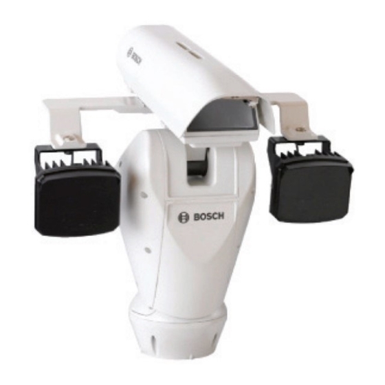
Page 28: Ir360 Models (Optional)
High-speed Positioning System IR360 Models (optional) The device must be configured to mount two of the Bosch UFLED illuminators. The illuminators are connected to the bracket supplied with the pan and tilt motor. CAUTION! For operational reasons, both spotlights must be fitted. -
Page 29: Assembling The Spotlights
Figure 5.6 Fitting the Spotlight on the Bracket Reference F.01U.164.491 | 2.0 | 2010.03 Description Bracket Spotlight holes Plane washer Crinkle washer Screw Description Gasket Bracket Spotlight Crinkle washer Screw Washer Installation Manual High-speed Positioning System Bosch Security Systems, Inc. -
Page 30: Infrared Led Spotlight Connections And Configurations
Disconnect the flat cable, disconnect the relay power supply connector, and remove the screws. Figure 5.7 LED Connections Reference Connect the power cable to the spotlight. Figure 5.8 Connecting the Power Cable to the Spotlight Bosch Security Systems, Inc. Description Flat cable Power supply connector Screws Installation Manual Connecting the Peripherals | en F.01U.164.491 | 2.0 | 2010.03... - Page 31 Figure 5.11 Inserting the Desiccant Bag Reference F.01U.164.491 | 2.0 | 2010.03 Description Flat cable Relay power supply connector Installation Manual High-speed Positioning System Bosch Security Systems, Inc.
- Page 32 Figure 5.13 Switching Day and Night Mode Reference NOTICE! The day/night mode relay is pre-wired. This drawing is for reference only. For more information on how to operate the day/night mode, please call technical support 1-800-326- 1450. Bosch Security Systems, Inc. Color Description Brown 24 VAC1...
-
Page 33: Configuring The Device
F.01U.164.491 | 2.0 | 2010.03 Description Factory Use Not Used, All Off Address RS485 Terminations Biphase + Bilinx Baud Rate Menu Setup (OSD) 2400 (8N 1) Preset 95 Auto AUX-On 200 Installation Manual High-speed Positioning System Bosch Security Systems, Inc. -
Page 34: Setting The Address
You can set the address for the UPH address using the Address switched (see item 3 in Figure 6.1). NOTICE! The highest addres using the Bosch OSRD protocol is 998. The highest address using the Pelco D protocol is 255. -
Page 35: Biphase/Bilinx Termination
AUX commands, i.e.: AUX ON - 46 - Enter (Dinion main menu) and AUX ON - 801 - Enter (Dinion installation menu). See 9 Keyboard Commands List - Bosch for more information about keyboard commands. - Page 36 3 Allegiant Matrix Switcher Figure 6.5 Typical Connections to a DiBos DiBos 8 Biphase UPH Series: unitized pan/tilt head Video output coax Bosch Security Systems, Inc. Biphase UPH Series: unitized pan/tilt head Video out, coax 4 LTC 8016 Bilinx Data Interface 5 Bilinx/Video...
- Page 37 | Configuring the Device Figure 6.6 VIPX1 Connection Diagrams Vidos, IE, DiBos 8, Bosch VMS or equivalent 5 Ethernet VIP X1 F.01U.164.491 | 2.0 | 2010.03 RS-485-2 Video UPH Series: unitized pan/tilt head Installation Manual High-speed Positioning System Bosch Security Systems, Inc.
-
Page 38: On-Screen Display (Osd)
Table 7.2 Accessing the DinionXF camera Setup Menu - AUX On 46 (screen may differ depending on NOTICE! Based on the model you are using, on-screen menus may vary slightly. Bosch Security Systems, Inc. option, then the Dinion > >... -
Page 39: Configuring The System
8 - DISPLAY PARAMETERS Table 8.2 Display Setup Menu F.01U.164.491 | 2.0 | 2010.03 > > > > > > : YES : YES : YES : YES : PAL : YES > > Installation Manual High-speed Positioning System Bosch Security Systems, Inc. -
Page 40: Area Parameters Menu
In the Text (String) Area menu, select the first line and enter the desired text. Note! If the area position start and end values are set to +0.00, this disables the text display (defaults are all set to +0.00). Bosch Security Systems, Inc. Description Shows the current position of the device (in degrees) with reference to the home position. - Page 41 PAN by +45 ° with respect to the system’s physical reference. Installation Manual High-speed Positioning System Default Options YES, NO Area 1 to Area 8 Area 1 to Area 8 +0.00 180.00to+ 180.00 Bosch Security Systems, Inc.
-
Page 42: Changing The Edit Text Menu
Note: To skip a space while in edit mode, press the Iris button, then move the joystick to the right past the number spaces you would like to skip. Press the Focus button to resume adding values. Bosch Security Systems, Inc. 0° 80°... -
Page 43: Display Parameters
2 - VIDEO CHARACTER TYPE 3 - HORIZONTAL DELTA 4 - VERTICAL DELTA 5 - ADDRSS NR. F.01U.164.491 | 2.0 | 2010.03 3GHI 4JKL 7STU 8VWX +,-. : YES : 000 : 000 : 000 Installation Manual High-speed Positioning System Bosch Security Systems, Inc. -
Page 44: Motion Parameters Menu
> 1 - PAN SPEED 2 - TILT SPEED 3 - ZOOM DEPENDENT SPEED Bosch Security Systems, Inc. Set to YES to superimpose the menu text over the video signal from the camera. Set to NO to have a blue screen behind the menu TEXT. -
Page 45: Limits
: + 0.00 : + 0.00 : + 0.00 : + 0.00 Installation Manual High-speed Positioning System Options 0.1-100.0* 0.1-100.0 0.1-100.0 0.1-100.0 0.1-100.0 0.1-100.0 0.1-100.0 Options 0.1-40.0* 0.1-40.0 0.1-40.0 0.1-40.0 0.1-40.0 0.1-40.0 0.1-40.0 Bosch Security Systems, Inc. -
Page 46: Preset/Patrol/Autopan
8 - MOTIONS RECALL Feature PRESET SPECIAL PRESET PARAMETER HOME POSITION PATROL Bosch Security Systems, Inc. Description Enables limits and values in degrees taken by the device in pan. Enables or disables complete rotation for scan/patrol/autopan movements (this function is useful when using... - Page 47 Message displayed when the preset position is reached. Installation Manual High-speed Positioning System Default Options -180.00° to +180.00° -40.00° to +90.00° YES, NO 00000 65535 00000 65535 00000 65535 040.0 .1 to 100.0°* 00001 00000 to 01000 sec. Bosch Security Systems, Inc.
- Page 48 Please note that through the normal Set Shot Command, only 99 presets can be stored. Use this menu for presets 100 to 250. MENU HOME > 1 - HOME POSITION 2 - REACHED SPEED Bosch Security Systems, Inc. : 20.0 : 20.0 : 100 :00005...
- Page 49 The random sequence is continually recalculated. Installation Manual High-speed Positioning System Default Options 00001 00001 to 00250 20.0 .1 to 100.0* Default Options 00001 00001 to 00250 00250 00001 to 00250 20.0 01 to 100.0°* YES, NO Bosch Security Systems, Inc.
- Page 50 (in seconds); by default the dwell is 50 seconds. MOTIONS RECALL MENU 1 - TIME ENABLING 2 - MOTION TYPE 3 - DWELL BEFORE ACT. : 00050 Bosch Security Systems, Inc. : 00002 : 00001 : 10.0 : 10.0 : 20.0...
-
Page 51: Wiper-Washer
Interval that the joystick is 00050 inactive before the movement setting is loaded. : NO : 00001 : 00002 : 00003 : 00005 : 00002 Installation Manual High-speed Positioning System Options YES, NO HOME, AUTOPAN, PATROL 00005 to 01000 sec. Bosch Security Systems, Inc. -
Page 52: Alarms
3 - ALARM 3 4 - ALARM 4 > 5 - ALARMS TEST Feature ACTION SHOW MESSAGE DURATION Bosch Security Systems, Inc. Description Enables the wiper function. Enables the preset position to be reached. Enables the relay to activate for water pump control. -
Page 53: Camera/Infrared Parameters
6 - MASK. 6 7 - MASK. 7 8 - MASK. 8 TEST MASK 1 Installation Manual High-speed Positioning System Default Options EDIT TEXT MENU > 1 - STRING EDIT ----------------------------- TEST MASK 1 ----------------------------- 2 - DELETE STRING Bosch Security Systems, Inc. -
Page 54: Infrared Parameters
Set the trip threshold of the two (2) illuminators (see Table 8.6). This is the preferred configuration when using the INTERNAL sensors. Figure 8.3 Setting the Trip Threshold Bosch Security Systems, Inc. Installation Manual Configuring the System | en F.01U.164.491 | 2.0 | 2010.03... -
Page 55: Load Default Configuration
Illuminator 2 - Adjust the sensitivity to the full clock-wise position. The unit will now be OFF when the telemetry input if OPEN (illuminator 1 if OFF), and ON when the telemetry input is CLOSED (illuminator 1 ON). Installation Manual High-speed Positioning System Bosch Security Systems, Inc. -
Page 56: Setup Info Menu
SETUP INFO MENU NET board ver. BOSCH xx mm/dd/yy HD r.x Protocol Baudrate Address Enabled RS485 FWInt xx Bosch Security Systems, Inc. : MPP board: ver. BOSCH xx mm/dd/yy HD r.x : BOSCH : 38400 : 00001 : TX-RX FWCam: xx... -
Page 57: Keyboard Commands List - Bosch
| Keyboard Commands List - Bosch Keyboard Commands List - Bosch Setup and Configuration Open OSD configuration: AUX ON - 200 - Enter Dinion main menu on: AUX ON - 46 - Enter Dinion installation menu on: AUX ON - 801 - Enter... -
Page 58: Changing The Settings
Changing the Settings To change a setting, proceed as follows: AUX ON - 200 - Enter to enable the OSD using Bosch protocol (Bilinx or Biphase connection); Pelco protocol (RS485-2 connection) uses 95 - PRESET. Move the cursor to the parameter to be changed. -
Page 59: Maintenance
T 4A L 250 V T 4A H 250 V T 4A L 250 V T 2A H 250 V Fuse F1 Fuse F2 T 4A L 250 V T 8A H 250 V Installation Manual High-speed Positioning System Bosch Security Systems, Inc. -
Page 60: Troubleshooting
It takes 30-45 seconds to cycle through this process, during which time there is no user control. Once it has finished the process and corrected for the effect of any environmental factors, the user regains full control. Bosch Security Systems, Inc. Possible Cause Solution... -
Page 61: Low And High Temperatures
(FPN) on the video signal. Solution: via Bilinx change the SensUp setting in the camera to OFF; this reduces the number and intensity of the blemishes. F.01U.164.491 | 2.0 | 2010.03 Installation Manual High-speed Positioning System Bosch Security Systems, Inc. -
Page 62: Dimensions And Range Of Movement
High-speed Positioning System Troubleshooting | en 11.2 Dimensions and Range of Movement 258 (10.16) 514 (20.24) Bosch Security Systems, Inc. Installation Manual F.01U.164.491 | 2.0 | 2010.03... - Page 63 | Troubleshooting High-speed Positioning System 514 (20.24) (2.87) Figure 11.1 Dimensions and Range of Movement F.01U.164.491 | 2.0 | 2010.03 Installation Manual Bosch Security Systems, Inc.
-
Page 64: A Appendix A: Wiring Summary
Reference AGND VIDEO RS-485-1 RS-485-2 Bosch Security Systems, Inc. Description Feed 1, 24 VAC for optional washer Feed 2, 24 VAC for optional washer Alarm 1 Input; triggered by external DC voltage Alarm 2 Input; triggered by external DC voltage Alarm 3 Input;... - Page 65 | Reference F.01U.164.491 | 2.0 | 2010.03 Description Biphase + (OSRD protocol) Biphase - (OSRD protocol) Installation Manual High-speed Positioning System Bosch Security Systems, Inc.
-
Page 66: B Appendix B: Connecting The Pump
Reference # Connecting a Washer System in the HAC-WAS05-20 For the connections, see the product installation handbook. Bosch Security Systems, Inc. Description Activation pump contact. O1 - C1: Clean contact output for starting the water pump (max. 50 VDC/30 VAC, 1 A). - Page 67 | High-speed Positioning System F.01U.164.491 | 2.0 | 2010.03 Installation Manual Bosch Security Systems, Inc.
- Page 69 Bosch Security Systems, Inc. www.boschsecurity.com © Bosch Security Systems, Inc., 2010; Data subject to change.
Need help?
Do you have a question about the UPH-C495N-L8120 and is the answer not in the manual?
Questions and answers