Table of Contents
Advertisement
Quick Links
Advertisement
Table of Contents

Subscribe to Our Youtube Channel
Related Manuals for La Marche A75R


Summary of Contents for La Marche A75R
- Page 1 La Marche Manufacturing Company www.lamarchemfg.com A75R SCR Battery Charger for Railroad Installation and Operation Manual 106 Bradrock Dr. Des Plaines, IL 60018-19671 Instruction Drawing Number: P25-LA75R-1 Tel: 847 299 1188 Fax: 847 299 3061 Revision A05 Rev. Date: 10/13 ECN: 20198...
-
Page 2: Electrical Safety
Important Safety Instructions Before using this equipment read all manuals and other documents related to this unit and other equipment connected to this unit. Always have a copy of a units manual on file nearby, in a safe place; if a replacement copy of a manual is needed it can be found at the www.lamarchemfg.com. -
Page 3: Unit Location
In the unlikely event of internal damage, please inform the carrier and contact La Marche for advice on the risk due to any damage before installing the product. Verify that you have all the necessary parts per your order for proper assembly. -
Page 4: Table Of Contents
Check for Damages ..........................iii Returns for Service ..........................iii Inspection Checklist ..........................iii Handling ..............................iii Table of Contents ............................iv A75R General Description ..........................1 Charger Overview ............................ 2 Installation ............................2 Mounting the A75R ........................3 Input/Output Connections ......................4 Customer Connections ........................ -
Page 5: A75R General Description
Remote shutdown allows you to place the charger offline for battery testing purposes. The A75R is equipped with AAR style hardware on the input and output connections. Temperature compensation is included standard to increase the longevity of the batteries and charger. -
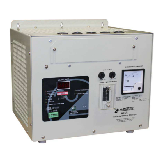
Page 6: Charger Overview
Charger Overview The A75R is simple and easy to use. It has an easy to read digital display for Output Voltage, and an analog meter for the Output Current. All settings on the A75R are done via the front panel DIP switches, so there is no need to navigate through confusing set up menus. -
Page 7: Installation
(or three) holes, appropriately sized for #10 hardware, for the keyholes. Attach the bolts (or screws) into the wall, lift the A75R onto the bolts, and tighten. Additionally the A75R has feet so it may simply be mounted on a floor, shelf or table that is appropriately sized for the chargers weight. -
Page 8: Input/Output Connections
Input/Output Connections After the A75R is mounted, the input and output connections can be made. The A75R is equipped with ¼” AAR style hardware for the input/output connections. The wire should be sized based on the AC and DC fuse sizes Figure 4 - Input/Output Connections Using Figure 4 above, Connect the AC input to the terminals shown as “1A”... -
Page 9: Operation
Operation Initial Startup Before applying AC power, be sure that the DC output DIP switches are set correctly see (Section 2.2). Once all connections have been made, and the output verified, the AC power may be turned on. The charger will automatically power up. -
Page 10: Adjustment Potentiometers
on position SW1 is used to disable the Charger’s Output. If this switch is toggled to the (switch pushed up), the unit output will drop to zero. SW2-SW10 are used to set the battery type and number of cells. Only one of these switches should be set to on at one time. -
Page 11: Status And Alarm Indicators
Status and Alarm Indicators The A75R front panel has six LED indicators as well as a three digit seven segment LED display. Additionally there is a analog DC ammeter for the output current. Figure 7 - Status and Alarm Indicators Current Limit –... -
Page 12: Quick Start Guide
Quick Start Guide... -
Page 13: General Maintenance Procedure
General Maintenance Procedure Yearly 1. Blow out rectifier/inverter with a low-pressure air hose. 2. Make sure all connections are tight. 3. Perform a visual check on all internal components. 4. Check front panel meters and alarms for accuracy. 4th Year REPEAT ABOVE WITH THE ADDITION OF: 1. -
Page 14: Manufacturer's Warranty
Special units are not returnable. In no event shall La Marche Manufacturing Co. have any liability for consequential damages, or loss, damage or expense directly or indirectly arising from the use of the products, or any inability to use them either separately or in combination with other equipment or materials, or from any other cause. -
Page 15: Document Control And Revision History
Document Control and Revision History Part Number: 115880 Instruction Number: P25-LA75R-1 Issue ECN: 17649 – 11/07 20198 – 10/13 20173 – 10/13 19399 – 01/12 18897 – 11/10 18017 – 10/08...
Need help?
Do you have a question about the A75R and is the answer not in the manual?
Questions and answers