Table of Contents
Advertisement
Your table saw has been engineered and manufactured to our high standards for dependability, ease of operation, and
operator safety. When properly cared for, it will give you years of rugged, trouble-free performance.
WARNING:
To reduce the risk of injury, the user must read and understand the operator's manual before using this
product.
Thank you for buying a RIDGID
SAVE THIS MANUAL FOR FUTURE REFERENCE
product.
®
OPERATOR'S MANUAL
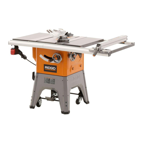
10 in. TABLE SAW
R4512
Advertisement
Table of Contents

Related Manuals for RIDGID R4512


Summary of Contents for RIDGID R4512
- Page 1 When properly cared for, it will give you years of rugged, trouble-free performance. WARNING: To reduce the risk of injury, the user must read and understand the operator’s manual before using this product. Thank you for buying a RIDGID product. ® SAVE THIS MANUAL FOR FUTURE REFERENCE...
-
Page 2: Table Of Contents
TABLE OF CONTENTS Introduction ..................................2 General Safety Rules ..............................3-4 Specific Safety Rules ..............................4-5 Symbols ..................................6-7 Electrical ..................................8-9 Glossary of Terms ................................10 Features ..................................11-13 Tools Needed ..................................14 Loose Parts ................................15-16 ... -
Page 3: General Safety Rules
GENERAL SAFETY RULES ALWAYS WEAR SAFETY GLASSES WITH SIDE WARNING: SHIELDS. Everyday eyeglasses have only impact- resistant lenses, they are NOT safety glasses. Read and understand all instructions. Failure to SECURE WORK. Use a featherboard to hold work when follow all instructions listed below, may result in electric shock, fire and/or serious personal injury. -
Page 4: Specific Safety Rules
GENERAL SAFETY RULES KEEP HANDS AWAY FROM CUTTING AREA. Keep use brake fluids, gasoline, petroleum-based products, or hands away from blades. Do not reach underneath any solvents to clean tool. work or around or over the blade while blade is rotating. ... - Page 5 SPECIFIC SAFETY RULES NEVER perform any operation “freehand” which means AVOID AWKWARD OPERATIONS AND HAND POSITIONS where a sudden slip could cause your hand using only your hands to support or guide the workpiece. Always use either the rip fence or miter fence to position to move into the cutting tool.
-
Page 6: Symbols
SYMBOLS Some of the following symbols may be used on this tool. Please study them and learn their meaning. Proper inter- pretation of these symbols will allow you to operate the tool better and safer. Indicates a potential personal injury hazard. Safety Alert To reduce the risk of injury, user must read and understand Read Operator’s Manual... -
Page 7: Save These Instructions
AUTHORIZED SERVICE CENTER for repair. When servic- If you do not understand the warnings and ing, use only identical replacement parts. instructions in the operator’s manual, do not use this product. Call RIDGID customer service for ® assistance. WARNING: The operation of any power tool can result in foreign objects being thrown into your eyes, which can result in severe eye damage. -
Page 8: Extension Cords
ELECTRICAL ExTENSION CORDS SPEED AND WIRING Use only 3-wire extension cords that have 3-prong ground- The no-load speed of this tool is approximately 3,450 rpm. This speed is not constant and decreases under a load or ing plugs and 3-pole receptacles that accept the tool's plug. with lower voltage. -
Page 9: Assembly
ASSEMBLY GroundinG WARNING: To prevent possible electrical hazards, have a qualified electrician check the line if you are not certain that it is properly wired. CHANGING MOTOR VOLTAGE See Figures 2 - 4. CoVer of Grounded WARNING: outlet box Electric shock can kill. To reduce the risk of seri- ous personal injury, never connect plug to power for uSe WitH 220-240 Volt Fig. -
Page 10: Glossary Of Terms
GLOSSARY OF TERMS Anti-Kickback Pawls (radial arm and table saws) Non-Through Cuts A device which, when properly installed and maintained, Any cutting operation where the blade does not extend is designed to stop the workpiece from being kicked back completely through the thickness of the workpiece. toward the front of the saw during a ripping operation. -
Page 11: Product Specifications
FEATURES PRODUCT SPECIFICATIONS No Load Speed ........3,450 r/min. (RPM) Blade Arbor .............. 5/8 in. Blade Diameter ............10 in. Cutting Depth at 0º: ..........3-1/4 in. Blade Tilt ..............0˚ - 45˚ Cutting Depth at 45º: ..........2-1/4 in. Rating ......... 120 V , 13 Amps, 60 Hz MITER SPREadER/ gaugE... - Page 12 FEATURES KNOW YOUR TABLE SAW MITER GAUGE - The miter gauge aligns the wood for a cross cut. The easy-to-read indicator shows the exact angle for a See Figure 5. miter cut, with adjustable stops at 90° and 45°. The safe use of this product requires an understanding of the information on the tool and in this operator’s manual as MITER GAUGE GROOVES - The miter gauge rides in the well as a knowledge of the project you are attempting.
-
Page 13: Operating Components
FEATURES OPERATING COMPONENTS WARNING: The upper portion of the blade projects up through the table and is surrounded by an insert called the throat plate. The ALWAYS make sure your workpiece is not in height of the blade is set with a handwheel on the front of the contact with the blade before operating the cabinet. -
Page 14: Tools Needed
TOOLS NEEDED The following tools (not included or drawn to scale) are needed for assembly and alignment: FRaMINg SquaRE PHILLIPS SCREWdRIVER FLaT BLadE SCREWdRIVER COMBINaTION SquaRE SOCKET WRENCH (8 mm, 13 mm SOCKET) WRENCH 4 mm, 8 mm, 10 mm, 13 mm, 14 mm C-CLaMP Fig. -
Page 15: Loose Parts
LOOSE PARTS The following items are included with the table saw: E, F Fig. 8 A. Blade Guard .............. 1 M. Rail Connector Bar ............ 3 B. Anti-Kickback Pawls ..........1 N. Table Extensions ............2 O. Spreader Bar ............. 1 C. - Page 16 LOOSE PARTS Fig. 9 A. Leg Stand Side Sections ........... 2 F. Rear Axle ..............1 B. Leg Stand Front and Back ......... 2 G. Front Axle ..............1 C. Outer Corners ............4 H. Rip Fence Storage Brackets ........2 D.
-
Page 17: Assembly
ASSEMBLY UNPACKING WARNING: This product requires assembly. If any parts are damaged or missing do not operate Carefully lift the saw from the carton and place it on a level this tool until the parts are replaced. Use of this work surface. - Page 18 ASSEMBLY INSTALLING THE TABLE EXTENSIONS See Figures 10 - 11. NOTE: It is helpful to place two inch-thick boards on the floor before lifting the saw table and motor housing from the box. This will make it easier to assemble parts, and to move the saw and set it upright.
- Page 19 ASSEMBLY ASSEMBLING THE LEG STANd oNTo THE Dust chute SAw CABINET See Figures 13 - 14. wARNING: Only install the dust chute when using a four inch dust collection system. Failure to heed this warning could result in serious personal injury or death. Clean saw dust from the cabinet regularly.
- Page 20 ASSEMBLY INSTALLING THE CASTER SET To THE LEG STANd feet See Figure 17. Slide the caster set into the leg stand, aligning the holes in the caster assembly with the holes in the leg stand. NoTE: Position the pedal as shown, so that it will be in ...
- Page 21 ASSEMBLY INSTALLING THE HEIGHT AdJUSTING bOlt HANdwHEEL See Figure 20. NoTE: The height adjusting handwheel knob and the bevel adjusting handwheel knob act as locks. To lock the wheel for KNOb operation, turn the knob clockwise until it is securely tightened. ...
- Page 22 ASSEMBLY INSTALLING THE BLAdE thrOat blaDe Plate See Figure 23 - 24. blaDe The blade and blade wrenches are located on the side of washer the saw in the storage area. Twist the knob counterclockwise to remove it. blaDe blaDe ...
-
Page 23: Rear Rail
ASSEMBLY INSTALLING/REMoVING THE THRoAT PLATE See Figure 25. blaDe thrOat To install the throat plate, slip the tab underneath the saw Plate table at the back of the saw and push down to secure in place. To remove the throat plate, place your index finger in the hole and lift the front end, pulling the throat plate out toward the front of the saw. - Page 24 ASSEMBLY INSTALLING THE RAILS oNTo THE SAw TABLE See Figures 29 - 32. Take the following from the large fastener pack: heX Nut 9 Hex head bolts (M8 x 30 for the front rail) 9 Bolts (M8 x 20 for the rear rail) 16 Nuts (M8: 10 for the front rail, 6 for the rear rail) NoTE: One M8 x 30 bolt, one M8 x 20 bolt, and four of the nuts will be needed to secure the spreader bar to the...
-
Page 25: Mounting The Switch Assembly
ASSEMBLY Lay a framing square on each side of the table top as framING square shown to make sure the table extensions are level with the top. If the table extensions and rails are flat and level, securely tighten the four center nuts on the front rail and the four center bolts on the rear rail. - Page 26 ASSEMBLY INSTALLING ENd CAPS See Figure 35. screws Align the end caps of the front rail to the end of the rail. Secure using self-tapping pan head screw (M4) in each frONt raIl hole using a Phillips screwdriver. eND caP Push rear rail end caps into position at each end of the ...
- Page 27 ASSEMBLY To INSTALL THE ANTI-KICKBACK PAwLS ANd blaDe BLAdE GUARd GuarD See Figures 37 - 39. wARNING: sPreaDer/ Replace dull or damaged anti-kickback pawls. rIVING KNIfe Dull or damaged pawls may not stop a kickback increasing the risk of serious personal injury. NoTE: Anti-kickback pawls should only be installed for GuarD through cuts.
- Page 28 ASSEMBLY To CHECK ANd ALIGN THE SPREAdER/ hOrIZONtal aDJustmeNt RIVING KNIFE ANd SAw BLAdE framING See Figure 40. square To check alignment of the spreader/riving knife: Unplug the saw. Raise the saw blade by turning the height/bevel adjusting handwheel clockwise.
-
Page 29: Operation
OPERATION CAUSES Of KICKBACK WARNING: Kickback can occur when the blade stalls or binds, kicking the workpiece back toward you with great force and speed. If Do not allow familiarity with tools to make you your hands are near the saw blade, they may be jerked loose careless. -
Page 30: Auxiliary Fence
OPERATION CUTTING AIDS See Figure 41. Push sticks are devices used for safely pushing a workpiece PUSH STICKS through the blade. They can be made in various sizes and shapes from scrap wood to use in a specific project. The stick must be narrower than the workpiece, with a 90˚... -
Page 31: How To Mount A Featherboard
OPERATION fEAThERBOARD hOW TO MOUNT A fEAThERBOARD See Figure 45. A featherboard is a device used to help control the workpiece by guiding it securely against the table or fence. Feather- Completely lower the saw blade. Position the rip fence to the boards are especially useful when ripping small workpieces desired adjustment for the cut to be performed and lock the and for completing non-through cuts. -
Page 32: Types Of Cuts
OPERATION TYPES Of CUTS See Figure 46. There are six basic cuts: 1) the cross cut, 2) the rip cut, 3) the miter cut, 4) the bevel cross cut, 5) the bevel rip cut, and 6) the compound (bevel) miter cut. All other cuts are combinations CrOSS CUT of these basic six. - Page 33 OPERATION hEIGhT ADjUSTING AND BEVEL ADjUSTING gULLeT hANDWhEEL KNOBS The height adjusting handwheel knob and bevel adjusting handwheel knobs act as locks. To unlock either knob before making an adjustment, turn the knob counterclockwise to loosen. After making a height or bevel adjustment, turn the knob clockwise to tighten.
- Page 34 OPERATION TO ADjUST ThE BEVEL INDICATOR See Figure 50. If the bevel indicator is not at zero when the saw blade is at 0°, adjust the indicator by loosening the screw and setting it at 0° on the bevel scale. Retighten the screw. SCrew WARNING: To reduce the risk of injury, always make sure the...
- Page 35 OPERATION TO SET ThE RIP fENCE SCALE INDICATOR SCaLe TO ThE BLADE SCrew See Figure 52. Use the indicator on the rip fence to position the fence along the scale on the front rail. NOTE: The anti-kickback pawls and blade guard assembly must be removed to perform this adjustment.
- Page 36 OPERATION hEELING (PARALLELING) ThE BLADE TO ThE MITER GAUGE GROOVE See Figures 54 - 56. rear PaneL WARNING: The blade must be square so the wood does not bind resulting in kickback. Failure to do so could result in serious personal injury. adjUSTIng Do not loosen any bolts for this adjustment until you have BOLTS (4)
-
Page 37: Making Cuts
OPERATION MAKING CUTS CrOSS CUT PLaCe LefT Hand On This table saw can perform a variety of cuts that are not all wOrKPIeCe and mentioned in this manual. DO NOT attempt to make any cuts MITer gaUge Here not covered here unless you are thoroughly familiar with the proper procedures and necessary accessories. - Page 38 OPERATION MAKING A RIP CUT rIP CUT See Figure 59. fenCe WARNING: BLade Make sure the blade guard assembly is installed and working properly to avoid serious possible injury. Set the blade to the correct depth for the workpiece. ...
- Page 39 OPERATION MAKING A BEVEL CROSS CUT vIewed frOM THe SIde, BeLOw THe TaBLe Saw See Figures 61 - 62. WARNING: Make sure the blade guard assembly is installed and working properly to avoid possible serious TO UnLOCK injury. WARNING: TO LOCK The miter gauge must be on the right side of the blade to avoid trapping the wood and causing BeveL LOCK...
- Page 40 OPERATION MAKING A BEVEL RIP CUT BeveL rIP CUT See Figure 63. rIP fenCe WARNING: BLade angLed Make sure the blade guard assembly is installed and working properly to avoid serious personal injury. WARNING: PUSH The rip fence must be on the right side of the blade STICK to avoid trapping the wood and causing kickback.
- Page 41 OPERATION COMPOUnd (BeveL) MITer CUT MAKING A COMPOUND (BEVEL) MITER CUT See Figure 64. PLaCe LefT Hand On MITer gaUge Here WARNING: Make sure the blade guard assembly is installed and working properly to avoid possible serious injury. WARNING: The miter gauge must be on the right side of the blade to avoid trapping the wood and causing kickback and the risk of serious personal injury.
- Page 42 OPERATION MAKING A NON-ThROUGh CUT nOn-THrOUgH CUT See Figure 66. BLade Non-through cuts (made with a standard 10 in. blade) can gUard reMOved be made with the grain (ripping) or across the grain (cross cut). The use of a non-through cut is essential to cutting grooves, rabbets, and dadoes.
- Page 43 OPERATION MAKING A DADO CUT dadO CUT See Figure 67. An optional dado throat plate is required for this procedure. All blades and dado sets must not be rated less than the speed of this tool. This saw is designed for use with an up to 8 in. stack dado (up to width of 13/16 in., with a maximum depth of cut of 1-1/2 in.).
- Page 44 OPERATION CONSTRUCTING A TABLE EXTENSION See Figure 68. 27 in. 14-5/8 in. You may construct a wood table extension to support larger workpieces. The finished height of the table extension should be 1-3/4 in. The finished length and width should be 3/4 in.
-
Page 45: Adjustments
adjustments CLOSED END bLaDE WRENCH WaRnInG: Before performing any adjustment, make sure OPEN END bLaDE the tool is unplugged from the power supply WRENCH and the switch is in the OFF ( O ) position. Fail- ure to heed this warning could result in serious personal injury. - Page 46 adjustments 0° aDJuStMENt tO set the blade at 0° and 45° SCREW See Figures 73 - 74. The angle settings of your saw have been set at the factory and, unless damaged in shipping, should not require set- ting during assembly. After extensive use, it may need to be bLaDE checked.
-
Page 47: To Check The Alignment Of The Rip Fence To The Blade
adjustments MItER tO adjust the mIteR GauGe KNOb GauGE baSE See Figure 75. You can set the miter gauge at 0° and plus or minus 45° with the miter gauge stop pin and adjustable stop screws. nOte: The miter gauge provides close accuracy in angled cuts. - Page 48 adjustments tO adjust the RIp Fence IndIcatOR See Figures 77 - 78. The rip fence has two indicators: one for use when the rip fence is on the right side of the saw blade and one for use when the rip fence is on the left side of the saw blade. nOte: The blade guard assembly must be removed to perform this adjustment.
-
Page 49: Maintenance
WaRnInG: WaRnInG: Do not at any time let brake fluids, gasoline, When servicing, use only identical RIDGID re- placement parts. Use of any other parts may petroleum-based products, penetrating oils, etc., come in contact with plastic parts. Chemicals can create a hazard or cause product damage. - Page 50 maIntenance cleanInG the dust chute Clean the dust chute periodically to remove sawdust. bOLt Using a 4 mm hex key, remove the screws that secure the back panel. Inspect the dust chute and attached dust collection devices to clear away sawdust or other debris. ...
-
Page 51: Troubleshooting
tROubleshOOtInG problem solution cause Excess vibration. Blade is out of balance. Replace blade. Blade is damaged. Replace blade. Saw is not mounted securely. Tighten all hardware. Work surface is uneven. Reposition on flat surface. Blade is warped. Replace blade. Rip fence does not move smoothly. Rip fence not mounted correctly. - Page 52 tROubleshOOtInG problem cause solution Saw does not make accurate Positive stops inside cabinet need Adjust positive stops. 90˚ or 45˚ cuts. adjusting (Bevel Cuts). Adjust the miter gauge. Miter gauge is misaligned (Miter Cuts). Height/bevel adjusting hand- Clean the gears or screw post. Gears or screw post inside wheel is hard to turn.
-
Page 53: Warranty
RIDGID, Inc. All warranty communications should be neglect, alteration, modification or repair by other than an directed to One World Technologies, Inc., attn: RIDGID Hand authorized service center for RIDGID branded hand held ®... -
Page 54: Customer Service Information
R4512 custOmeR seRVIce InFORmatIOn For parts or service, contact your nearest RIDGID authorized service center. Be sure to provide all relevant information when you call or visit. For the location of the authorized service center nearest you, please call 1-866-539-1710 or visit us online at www.ridgid.com.
Need help?
Do you have a question about the R4512 and is the answer not in the manual?
Questions and answers
I have this exact model Ridgid table saw R4512 with 4 casters and trying to align the sawblade parallel to the miter gauge slot using an indicator tool and it won't budge after loosening the tree bolts on the trunnion under the table saw top.
If the trunnion bolts on your RIDGID R4512 table saw won't budge when trying to align the blade parallel to the miter gauge slot, you can try the following steps:
1. Loosen the Trunnion Bolts Properly – Ensure you are loosening all the necessary trunnion bolts. Sometimes they may be overly tight from the factory or previous adjustments.
2. Use Washers and Lubrication – Adding steel washers on each bolt with lithium grease between them can help reduce friction, allowing the trunnion to move more freely when making adjustments.
3. Apply Gentle Force – If the trunnion still won't move, you may need to tap it gently with a mallet or apply controlled pressure to shift it into alignment.
4. Use PALS (Precision Alignment System) – Installing a PALS kit can make fine adjustments easier by helping control the movement of the trunnion while preventing it from creeping out of position when tightening the bolts.
5. Check for Obstructions – Ensure there are no debris or obstructions preventing the trunnion from moving.
Following these steps should help you align the blade parallel to the miter gauge slot.
This answer is automatically generated
Is this saw a belt driven or a direct drive were the blade is mounted on the motor itself?
The RIDGID R4512 table saw is belt driven.
This answer is automatically generated