Table of Contents
Advertisement
Your table saw has been engineered and manufactured to our high standards for dependability, ease of operation, and
operator safety. When properly cared for, it will give you years of rugged, trouble-free performance.
WARNING:
To reduce the risk of injury, the user must read and understand the operator's manual before using this
product.
Thank you for buying a RIDGID
SAVE THIS MANUAL FOR FUTURE REFERENCE
product.
®
OPERATOR'S MANUAL
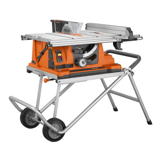
10 in. TABLE SAW
R4510 / R45101
Advertisement
Table of Contents
Troubleshooting

Related Manuals for RIDGID R4510


Summary of Contents for RIDGID R4510
- Page 1 When properly cared for, it will give you years of rugged, trouble-free performance. WARNING: To reduce the risk of injury, the user must read and understand the operator’s manual before using this product. Thank you for buying a RIDGID product. ® SAVE THIS MANUAL FOR FUTURE REFERENCE...
-
Page 2: Table Of Contents
TABLE OF CONTENTS Introduction..................................2 General Safety Rules ..............................3-4 Specific Safety Rules ..............................4-5 Symbols .................................... 6 Electrical ................................... 7 Glossary of Terms ................................8 Features ..................................9-11 Tools Needed .................................. 13 Loose Parts ................................14-22 ... -
Page 3: General Safety Rules
GENERAL SAFETY RULES SECURE WORK. Use clamps or a vise to hold work when WARNING: practical. It’s safer than using your hand and frees both hands to operate tool. Read and understand all instructions. Failure to follow all instructions listed below, may result in ... -
Page 4: Specific Safety Rules
GENERAL SAFETY RULES INSPECT TOOL CORDS PERIODICALLY. If damaged, STAY ALERT AND EXERCISE CONTROL. Watch what have repaired by a qualified service technician at you are doing and use common sense. Do not operate an authorized service facility. The conductor with tool when you are tired. - Page 5 SPECIFIC SAFETY RULES MOVE THE RIP FENCE out of the way when cross cut- MAKE SURE THE WORK AREA HAS AMPLE LIGHTING to see the work and that no obstructions will interfere with ting. safe operation BEFORE performing any work using the ...
-
Page 6: Symbols
SYMBOLS The following signal words and meanings are intended to explain the levels of risk associated with this product. SYMBOL SIGNAL MEANING Indicates an imminently hazardous situation, which, if not avoided, will result DANGER: in death or serious injury. Indicates a potentially hazardous situation, which, if not avoided, could result WARNING: in death or serious injury. -
Page 7: Electrical
ELECTRICAL EXTENSION CORDS SPEED AND WIRING Use only 3-wire extension cords that have 3-prong ground- The no-load speed of this tool is approximately 4,400 rpm. ing plugs and 3-pole receptacles that accept the tool's plug. This speed is not constant and decreases under a load or with lower voltage. -
Page 8: Glossary Of Terms
GLOSSARY OF TERMS Anti-Kickback Pawls (radial arm and table saws) Push Blocks (for jointer planers) A device which, when properly installed and maintained, Device used to feed the workpiece over the jointer planer is designed to stop the workpiece from being kicked back cutterhead during any operation. -
Page 9: Features
FEATURES PRODUCT SPECIFICATIONS Blade Diameter ............10 in. Cutting Depth at 45° ..........2-1/2 in. Blade Arbor ...............5/8 in. Rating ...........120 V~, 15 Amps, 60 Hz Cutting Depth at 90° ..........3-1/2 in. No Load Speed ........4,400 r/min. (RPM) RIVING BLADE GUARD KNIFE ASSEMBLY... - Page 10 FEATURES KNOW YOUR TABLE SAW BLADE GUARD - Always keep the guard down over the blade for through-sawing cuts. See Figure 3. BLADE HEIGHT LOCK KNOB - This knob, in the center of The safe use of this product requires an understanding of the bevel adjusting handwheel, locks the height of the blade.
-
Page 11: Features
FEATURES OPERATING COMPONENTS WARNING: The upper portion of the blade projects up through the table and is surrounded by an insert called the throat plate. The ALWAYS make sure your workpiece is not in height of the blade is set with a handwheel on the front of contact with the blade before operating the switch the cabinet. -
Page 12: Tools Needed
TOOLS NEEDED The following tools (not included or drawn to scale) are needed for assembly and adjustments: FRAMING SQUARE PHILLIPS SCREWDRIVER FLATHEAD SCREWDRIVER C-CLAMPS COMBINATION SQUARE Fig. 5 LOOSE PARTS LIST The following items are included with your table saw: ANTI-KICKBACK RIP FENCE PAWLS... -
Page 13: Loose Parts List
LOOSE PARTS LIST UPPER CENTER TUBE BRACE HANDLE SECTION FLAT WASHER, SMALL LOCK WHEEL LOCK CARRIAGE SCREW BOLT LARGE SPACER SMALL SPACER FLAT WASHER, LARGE OUTER TUBE INNER LEG ASSEMBLY Fig. 7... -
Page 14: Assembly
ASSEMBLY UNPACKING WARNING: This product requires assembly. Do not connect to power supply until assembly Carefully lift the saw from the carton and place on a level is complete. Failure to comply could result in work surface. accidental starting and possible serious personal NOTE: This tool is heavy. -
Page 15: Assembling The Leg Stand
ASSEMBLY Insert a carriage bolt through the top hole of the inner leg ASSEMBLING THE LEG STAND assembly then slide a spacer on the bolt. Repeat for the See Figure 8. other side. Many of the leg stand parts are movable. All hardware must Slide the center brace onto the bolt and secure in place be tightened securely but not so tight that the leg stand won’t using a lock nut. - Page 16 ASSEMBLY MOUNTING THE LEG STAND ON THE TABLE BOLT SAW BASE See Figure 9. WARNING: Do not lift the saw without help. The saw base weighs approximately 75 lbs. Hold it close to your body. Keep your knees bent and lift with your legs, not your back.
- Page 17 ASSEMBLY TO OPEN THE LEG STAND See Figures 10 - 12 Grasp the grips on the saw table and stand it upright as shown below. Step on the release lever and pull the grips toward you at the same time. ...
-
Page 18: To Secure/Level Saw
ASSEMBLY TO SECURE/LEVEL THE SAW See Figure 13. With the leg stand open and the table saw resting on a flat, level surface, the saw should not move or rock from side RIP FENCE to side. If the saw rocks from side to side, the leveling feet need adjusting until the leg stand is balanced. - Page 19 ASSEMBLY TO CLOSE THE LEG STAND AND MOVE THE See Figures 16 - 19. Remove any workpieces from the tool. Remove and securely store any tools or accessories such as rip fence, miter gauge, clamps, blade guard, etc. Lower the saw blade.
-
Page 20: To Change Riving Knife Positions
ASSEMBLY TO REMOVE/REPLACE/ALIGN THE THROAT PLATE See Figure 20. WARNING: The throat plate must be level with the saw table. If the throat plate is too high or too low, the workpiece can catch on the uneven edges resulting SET SCREWS in binding or kickback which could result in serious Fig. -
Page 21: To Check Saw Blade Installation
ASSEMBLY TO CHECK SAW BLADE INSTALLATION BLADE BLADE WRENCH See Figure 22. WRENCH (RIGHT) SCREW (LEFT) CAUTION: To work properly, the saw blade teeth must point down toward the front of the saw. Failure to heed this warning could cause damage to the saw blade, the saw, or the workpiece. -
Page 22: To Check/Align Riving Knife/Saw Blade
ASSEMBLY To install blade guard: Lift the guard lever up to unlock. With the front of the blade guard raised, lower the back of the guard into the middle hole of the riving knife. Push the front of the guard down until it is parallel to the table (see figure 24). -
Page 23: Operation
OPERATION CAUSES OF KICKBACK WARNING: Kickback can occur when the blade stalls or binds, kicking Do not allow familiarity with tools to make you the workpiece back toward you with great force and speed. If careless. Remember that a careless fraction of a your hands are near the saw blade, they may be jerked loose second is sufficient to inflict serious injury. -
Page 24: Cutting Aids
OPERATION CUTTING AIDS See Figure 26. Push sticks are devices that may be used for pushing a workpiece through the blade in any rip cut. When making non-through cuts or ripping narrow stock, always use a PUSH STICKS push stick, push block, and/or featherboard so your hands do not come within 3 inches of the saw blade. -
Page 25: Cutting Tips
OPERATION TYPES OF CUTS See Figure 29. There are six basic cuts: 1) the cross cut, 2) the rip cut, 3) the miter cut, 4) the bevel cross cut, 5) the bevel rip cut, and 6) the compound (bevel) miter cut. All other cuts are combinations of these basic six. - Page 26 OPERATION FEATHERBOARD HOW TO MOUNT A FEATHERBOARD See Figure 31. A featherboard is a device used to help control the workpiece by guiding it securely against the table or fence. Featherboards Completely lower the saw blade. Position the rip fence to the are especially useful when ripping small workpieces and for desired adjustment for the cut to be performed and lock the completing non-through cuts.
- Page 27 OPERATION TO CHANGE BLADE DEPTH GULLET See Figure 32. The blade depth should be set so that the outer points of the saw blade are higher than the workpiece by approximately 1/8 in. to 1/4 in. but the lowest points (gullets) are below the workpiece.
- Page 28 OPERATION IND-I-CUT Using a sharp pencil, mark a line on the disc at the edge of the freshly cut wood. NOTE: These lines indicate the path of the cut made by the saw blade. When the blade is changed, these lines will need to be erased and reset.
- Page 29 OPERATION TO USE THE MICRO-ADJUST WHEEL ON THE RIP FENCE See Figure 38. The micro-adjust wheel on the rip fence allows the user to make one-handed adjustments. Unlock the locking lever by lifting the lever. Push in on the micro-adjust wheel and rotate to the de- sired location.
- Page 30 OPERATION MITER GAUGE HEELING (PARALLELING) THE BLADE TO THE COMBINATION GROOVE SQUARE MITER GAUGE GROOVE See Figures 41 - 43. WARNING: The blade must be square so the wood does not bind resulting in kickback. Failure to do so could result in serious personal injury.
-
Page 31: Making Cuts
OPERATION MAKING CUTS CROSS CUT The blade provided with your saw is a high-quality combi- PLACE RIGHT HAND nation blade suitable for ripping and cross cut operations. MITER GAUGE HERE Carefully check all setups and rotate the blade one full revolution to assure proper clearance before connecting saw to power source. - Page 32 OPERATION MAKING A RIP CUT RIP CUT See Figure 46. RIP FENCE BLADE PUSH WARNING: STICK Make sure the blade guard assembly is installed and working properly to avoid serious personal injury. Set the blade to the correct depth for the workpiece. PUSH ...
- Page 33 OPERATION VIEWED FROM THE FRONT, BELOW THE TABLE SAW MAKING A BEVEL CROSS CUT See Figures 48 - 49. LOCK UNLOCK WARNING: Make sure the blade guard assembly is installed and working properly to avoid serious personal injury. WARNING: The miter gauge must be on the right side of the blade to avoid trapping the wood and causing kickback.
- Page 34 OPERATION MAKING A BEVEL RIP CUT BEVEL RIP CUT See Figure 50. BLADE FENCE WARNING: ANGLED The rip fence must be on the right side of the blade to avoid trapping the wood and causing kickback. Placement of the rip fence to the left of the blade will result in kickback and the risk of serious personal injury.
- Page 35 OPERATION LARGE PANEL CUT MAKING A COMPOUND (BEVEL) MITER CUT See Figure 51. SUPPORTS FENCE WARNING: Make sure the blade guard assembly is installed and working properly to avoid serious personal injury. WARNING: The miter gauge must be on the right side of the blade to avoid trapping the wood and causing kickback.
- Page 36 OPERATION MAKING A NON-THROUGH CUT NON-THROUGH CUT See Figure 53. BLADE GUARD Non-through cuts (made with a standard 10 in. blade) can be REMOVED made with the grain (ripping) or across the grain (cross cut). PUSH STICK The use of a non-through cut is essential to cutting grooves, rabbets, and dadoes.
-
Page 37: Operation
OPERATION DADO CUT MAKING A DADO CUT See Figure 54. An optional dado throat plate is required for this procedure (refer to the Accessories section later in this manual and check with the retailer where the table saw was purchased). All blades and dado sets must not be rated less than the speed of this tool. -
Page 38: Adjustments
ADJUSTMENTS BLADE BLADE WARNING: WRENCH WRENCH (RIGHT) (LEFT) Before performing any adjustment, make sure the tool is unplugged from the power supply. Failure to heed this warning could result in seri- ous personal injury. To avoid unnecessary set-ups and adjustments, a good practice is to check your setups carefully with a framing square and make practice cuts in scrap wood before making finish cuts in good workpieces. - Page 39 ADJUSTMENTS TO SET THE BEVEL INDICATOR AND BEVEL BLADE AT 0˚ POSITION STOPS AT 0˚ AND 45˚ BEVEL LOCKING See Figures 57 - 60. LEVER The angle settings of the saw have been set at the factory and, unless damaged in shipping, should not require set- ting during assembly.
- Page 40 ADJUSTMENTS If blade is not 45º to the table: Loosen 45º stop screw until it is even with the top of the 45˚ STOP saw table using a hex key. SCREW Release the bevel locking lever and position the bevel adjusting handwheel until blade is 45º...
-
Page 41: To Check/Djust Alignment Of Rip Fence
ADJUSTMENTS TO CHECK AND ADJUST THE ALIGNMENT OF COMBINATION SQUARE THE RIP FENCE See Figures 63 - 65. The rip fence must be parallel to the saw blade and the miter gauge grooves. WARNING: A misaligned rip fence can cause kickbacks and jams. -
Page 42: Adjustments
ADJUSTMENTS TO ADJUST THE BEVEL LOCKING LEVER See Figure 66. Release bevel locking lever and bevel saw blade to 45º. Push bevel locking lever to lock blade into place. With moderate force, attempt to move the bevel adjusting handwheel toward the 0º... -
Page 43: Lubrication
MAINTENANCE WARNING: When servicing, use only identical replacement parts. Use of any other parts may create a hazard or cause product damage. WARNING: Always wear eye protection with side shields marked to comply with ANSI Z87.1 during product operation. If operation is dusty, also wear a dust mask. -
Page 44: Accessories
MAINTENANCE BRUSH REPLACEMENT BRUSH See Figure 70. Unplug the saw. BRUSH ASSEMBLY Lower blade completely and bevel to 45º. Lock the blade. Turn saw upside down. Remove brush caps with a screwdriver. NOTE: Brush assembly is spring load and will pop out when brush cap is removed. -
Page 45: Troubleshooting
TROUBLESHOOTING Problem Cause Solution Excess vibration. Blade is out of balance. Replace blade. Blade is damaged. Replace blade. Saw is not mounted securely. Tighten all hardware. Work surface is uneven. Reposition on flat surface. Blade is warped. Check saw blade installation. Rip fence does not move smoothly. -
Page 46: Troubleshooting
TROUBLESHOOTING Problem Cause Solution See To Set the Bevel Indicator and Saw does not make 0˚ or 45˚ cuts. Bevel stops not properly adjusted. Bevel Stops at 0˚ and 45˚ (Squaring the Blade) in the Adjustments section. See To Adjust the Miter Gauge in the Miter gauge is misaligned (Miter Adjustments section. -
Page 47: Warranty
RIDGID, Inc. All warranty communications should be neglect, alteration, modification or repair by other than an directed to One World Technologies, Inc., attn: RIDGID Hand authorized service center for RIDGID branded hand held ®... - Page 48 R4510 / R45101 CUSTOMER SERVICE INFORMATION For parts or service, contact your nearest RIDGID authorized service center. Be sure to provide all relevant information when you call or visit. For the location of the authorized service center nearest you, please call 1-866-539-1710 or visit us online at www.ridgidwoodworking.com.
Need help?
Do you have a question about the R4510 and is the answer not in the manual?
Questions and answers