Table of Contents
Advertisement
Advertisement
Table of Contents

Related Manuals for Martin RoboScan Pro 518


Summary of Contents for Martin RoboScan Pro 518
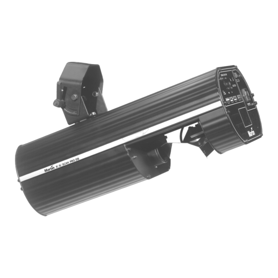
- Page 1 RoboScan Pro 518 user manual...
- Page 2 © 1998-2000 Martin Professional A/S, Denmark. All rights reserved. No part of this manual may be reproduced, in any form or by any means, without permission in writing from Martin Professional A/S, Denmark. Printed in Denmark. P/N 35000059 Rev. D...
-
Page 3: Table Of Contents
1 Introduction RoboScan Pro 518 Safety Information ..............4 Features .......................5 Accessories ......................5 section 2 Installation Installing and Changing the Lamp ................6 Checking Voltage and Frequency Settings ............6 Installing a Plug on the Power Cord ..............7 Releasing the Pan/Tilt Lock ..................7 Rigging .........................7... -
Page 4: Roboscan Pro 518 Safety Information
This manual covers the RoboScan Pro 518 with software version 6.4. The latest information on the RoboScan Pro 518 is always available from your dealer and the Martin web site at http://www.martin.dk. R o b o S c a n P r o 5 1 8 S a f e t y I n f o r m a t i o n W A R N I N G ! This product is for professional use only. -
Page 5: Features
Power factor correction for low current consumption • Overheating protection A c c e s s o r i e s Your Martin dealer can provide you with the following RoboScan Pro 518 accessories: • Optional gobo set (6 pcs)................. P/N 43010007 Introduction... -
Page 6: Installation
I n s t a l l i n g a n d C h a n g i n g t h e L a m p The RoboScan Pro 518 is designed to use the Osram HSD 250 and Philips MSD-250/2 dis- charge lamps. -
Page 7: Installing A Plug On The Power Cord
W A R N I N G ! For safe operation, the fixture must be grounded (earthed). The RoboScan Pro 518 may be delivered without a plug on the power cord. Following the manufacturer’s instructions, install an approved 3-prong grounding-type plug that fits your supply. -
Page 8: Setup For Controller Operation
DMX controllers usually have 5-pin XLR outputs and are wired with pin 2 cold (-) and pin 3 hot (+). Martin-standard controllers have 3-pin XLR outputs wired with pin 2 hot (+) and pin 3 cold (-). The Pro 518’s XLR input is config- ured for the Martin standard. - Page 9 The address may be any channel between 1 and 32. DMX mode: The RoboScan Pro 518 may be operated in 3 DMX modes; see the DMX pro- tocol starting on page 18 for details. It uses 7 consecutive DMX channels in mode 1, and 9 consecutive DMX channels in modes 2 and 3.
-
Page 10: Operation
S t a n d - A l o n e O p e r a t i o n The Roboscan Pro 518 may be operated without a controller in stand-alone mode. In this mode, the fixture performs a random sequence that is triggered by the beat of the music or at a set speed. - Page 11 A relay inside the fixture allows you to turn on and off the lamp via the controller without affecting the rest of the fixture. After switching on the RoboScan Pro 518, the lamp will remain off until you send a “lamp on” command from the controller.
-
Page 12: Focus
Beginning with software version 6.4, an improved speed array has been programmed for use with the Martin controllers. This increases the range of speeds available for controlling effects. To use this feature, the DMX-mode jumper must be set to mode 3. This is the fac- tory default setting. -
Page 13: Service And Maintenance
A d j u s t i n g t h e L a m p The RoboScan Pro 518 comes fully adjusted from the factory, however, readjustment of the lamp may be necessary due to differences between lamps. The lamp is adjusted by turning the 3 Phillips-head screws on the lamp access plate. -
Page 14: Dmx Mode Selection
DMX Mode Selection The DMX mode is set by a jumper inside the RoboScan Pro 518. The factory default is mode 3 (jumper on pins 4 and 5). Follow the procedure below to enable modes 1 or 2. -
Page 15: Selecting Voltage And Frequency
Selectable Selectable Model Voltages Frequencies RoboScan Pro 518 EU 230 V / 240 V / 250 V 50 Hz RoboScan Pro 518 US 100 V / 110 V / 120 V 50/60 Hz... -
Page 16: Adjusting The Mirror
Adjusting the Mirror Readjusting the mechanical stop on the RoboScan Pro 518 mirror adaptor is required if the pan or tilt motor occasionally loses step, leaving the mirror incorrectly positioned after a reset. This error occurs when the recoil of the mechanical reset bounces the mirror and bracket a whole pan or tilt motor step. - Page 17 Carefully turn the motor and mirror clockwise (make sure the motor axle does not turn) until there is a distance of 1/2 to 1 mm (1/64 - 1/32”) between the edge of the mirror bracket (C2) and the top mechanical stop (C1).
-
Page 18: Dmx 512 Protocol
For smooth movement in vector mode, the controller’s fade time must be set to 0, i.e., the position must bump from the current value to the next. If the RoboScan Pro 518 is set to run vector mode, tracking mode can be enabled by programming the speed channels to 0. - Page 19 Channel Mode Mode Mode Values Percent Effect Color 0 - 3 0 - 1 White 4 - 7 2 - 3 White / Pink split 8 - 11 3 - 4 Pink 12 - 15 5 - 6 Pink / Magenta split 16 - 19 6 - 7 Magenta...
- Page 20 Tracking Fast Æ Slow 1 - 251 0 - 98 252 - 255 99 - 100 Blackout while moving Dimmer Speed Fast Æ Slow 0 - 251 0 - 98 252 - 255 99 - 100 Fast RoboScan Pro 518...
- Page 21 a p p e n d i x b S P E C I F I C A T I O N S D i m e n s i o n s • Length:....................533 mm (21.0") • Height with bracket: ................325 mm (12.8") •...
- Page 22 E X T E R I O R V I E W (dimensions in millimeters) wrap safety wire bracket mounting bolts through bracket (clamp not shown) DIP switch lamp access plate serial number label AC input & fuse lamp adjustment screws RoboScan Pro 518...
- Page 23 a p p e n d i x d D I P - S W I T C H TA B L E This table shows DIP-switch settings for channels 1- 511. To find a setting, locate the chan- nel in the table. Follow the row to the left to find the settings for pins 1 through 5; follow the column to the top to find the settings for pins 6 through 9.
Need help?
Do you have a question about the RoboScan Pro 518 and is the answer not in the manual?
Questions and answers