Advertisement
42-159
-20-
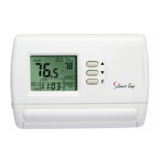
Smart Temp 42-159
SINGLE STAGE PROGRAMMABLE THERMOSTAT
1 Heat / 1 Cool single stage thermostat.
5+2 Programmable, Compatible with heat pump system
Installation and Operation Manual
Specification:--------------------------------------------------------------------------------
Power Supply:
20VAC-30VAC 50-60HZ or Battery powered.
Terminal Load:
1.0A per terminal, 3.0A maximum total load
Set Point Temperature Range:
7ºC to 32ºC
Accuracy:
+/- 1ºF or +/- 0.5ºC.
Dimensions:
13.0cm W X 9.4cm H X 3.0cm D
Color:
White
FEATURES:---------------------------------------------------------------------------------
LCD display with backlight, continuous backlight option
Simultaneous heat and cool set point storage
Display of room temperature, set temperature and current time simultaneously
Fan switch with ON and AUTO
Permanent user setting retention during power loss. No batteries are required.
Operates from 24VAC, or from 2 size "AAA" alkaline batteries
Optional temperature display of Fahrenheit or Celsius scale.
Air Filter change Indicator
Low Battery Indicator
Display temperature calibration.
Separate 5-day (weekday) and 2-day (Saturday/Sunday) programming with four
separate time/temperature periods per day.
Intelligent Recovery Option for optimizing comfort
IMPORTANT SAFETY INFORMATION-------------------------------------------
Always turn off power at the main power source by removing the fuse, or
switching the circuit breaker to the off position before installing, removing,
cleaning, or servicing this thermostat.
Read all of the information in this manual before installing this thermostat.
Use a professional contractor to install this thermostat.
This is a 24VAC low-voltage thermostat. DO NOT INSTALL ON VOLTAGES
HIGHER THAN 30 VAC.
ALL wiring must conform to local and national building and electrical codes and
ordinances.
Do not short (jumper) across terminals on the gas valve or at the system control to
test installation. This will damage the thermostat and void the warranty.
Do not switch the system to cool if the temperature is below 10ºC. This can
damage the air conditioning system and may cause personal injury.
Replace batteries when the battery icon indicates the low battery message.
Use this thermostat only as described in this manual.
-1-
Aug-10-2011
Advertisement
Table of Contents

Subscribe to Our Youtube Channel
Related Manuals for Smart temp 42-159


Summary of Contents for Smart temp 42-159
- Page 1 Smart Temp 42-159 SINGLE STAGE PROGRAMMABLE THERMOSTAT 1 Heat / 1 Cool single stage thermostat. 5+2 Programmable, Compatible with heat pump system Installation and Operation Manual Specification:-------------------------------------------------------------------------------- Power Supply: 20VAC-30VAC 50-60HZ or Battery powered. Terminal Load: 1.0A per terminal, 3.0A maximum total load Set Point Temperature Range: 7ºC to 32ºC...
- Page 2 Refer to the following section for instructions on how to install this thermostat. INSTALL THE THERMOSTAT--------------------------------------------------------------------------------- ATTACH THERMOSTAT BASE TO WALL PULL THE COVER OFF THE BASE. fan option switch screw anchor ELEC base reset screw OPEN cover Figure 2 Figure 1 -19- 42-159 Aug-10-2011...
- Page 3 12. Replace the cover on the thermostat by snapping it in place. 13. Turn on power to the system at the main service panel. 14. Test thermostat operation as described in the following section. -18- 42-159 Aug-10-2011...
-
Page 4: Warranty Policy
Figure 3, Typical wiring diagram for heat/cool, 5 wire two transformer systems. -17- 42-159 Aug-10-2011... - Page 5 Move the system switch to the OFF position. If your system does not have a “G” (Fan) terminal connection, skip to the Heating System. Move the fan switch to the ON position. The blower should begin to operate. Move the fan switch to the AUTO position. The blower should stop immediately. -16- 42-159 Aug-10-2011...
- Page 6 Install two “AAA” alkaline batteries in the battery compressor lock-out option is selected in the compartment. Be sure to match the positive (+) ends of the configuration menu. batteries with the positive terminals marked in the battery compartment. -15- 42-159 Aug-10-2011...
-
Page 7: Configuration And Operation
(17) Indicates the thermostat is calling for HEAT or COOL Intelligent Recovery Option. “1” = Active PRGM 0 or 1 “0” = Deactivated. (18) Indicates the current system switch position Default = 0 Return to normal operation -14- 42-159 Aug-10-2011... - Page 8 0 or 5 minutes. When the thermostat (8) Fan Control Switch (AUTO/ON) compressor time delay occurs, the Cool On or Heat On display will flash during compressor lockout. (9) System Control Switch (COOL/OFF/HEAT) -13- 42-159 Aug-10-2011...
-
Page 9: Thermostat Operation
Press the ▲ and ▼ buttons to select the desired room temperature. The thermostat will override the current programming and keep the Room temperature at the selected temperature until the next program period begins. The thermostat will then revert back to the program temperatures. -12- 42-159 Aug-10-2011... - Page 10 1 heating period (flashing),and the currently programmed temperature. 9) Repeat steps 3 thru 7 to complete Saturday and Sunday programming. 10) When you have completed entering your heating program, press RUN. -10- -11- 42-159 Aug-10-2011...
Need help?
Do you have a question about the 42-159 and is the answer not in the manual?
Questions and answers