Table of Contents
Advertisement
Quick Links
Advertisement
Table of Contents

Subscribe to Our Youtube Channel
Related Manuals for Smart temp SMT - 131


Summary of Contents for Smart temp SMT - 131
- Page 1 SMT - 131 Manual Ver 1.1...
- Page 2 Revision History Version 1 Original Document Version 1.1 Added Mode select in modbus Index Index Introduction Thermostat operation Installation Wiring Examples – HVAC Control Wiring Examples – Ancillary Functions Installer Options Menu Modbus Data Specifications Page 2...
-
Page 3: Thermostat Operation
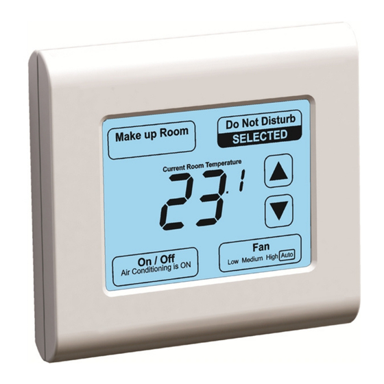
Introduction The Smart Temp SMT-131 thermostat has been designed for use in hotel rooms and other locations where the user may be unfamiliar with thermostat operations. In these applications it is important that the thermostat be very intuitive, robust and attractive. The SMT-131 thermostat has been designed with these important goals is mind. - Page 4 Note. Option 16 in the installer menu (See page 11) permits you to set the SMT-131 to reset the indoor fan to Automatic Mode (cycle on and off with heating and cooling) every time the thermostat is turned off and then back on. Ventilation Mode If permitted by DIP Sw7, (See page 5) the user can run the indoor fan only (Ventilation Mode) when the SMT-131 is off by tapping the fan button.
- Page 5 DIP Switch Settings Switch Function Indoor Fan Mode 3 Fan Speed 1 Fan Speed Equipment Type Heat Pump Heat Cool HP Mode (Sw2= ON) Rev Valve Heat (B) Rev Valve Cool (O) HC Mode (Sw2=OFF) HE – Fan With Heat HG –...
- Page 6 Heat Cool System - 1 Fan Speed Switch Settings Sw1 = Off - 1 Fan speed Sw2 = Off - HC Mode Sw3 = On/HE Off/HG Sw4 = N/A Sw5 = On - Comp Delay Sw6 = Customer Pref Sw7 = Customer Pref 0-10V Heating Valve With Cool - 1 Fan Speed Switch Settings Sw1 = Off - 1 Fan Speed...
- Page 7 3°C from set point. The output is linear. Wiring Examples – Ancillary Functions Additional capabilities can be used when wiring the SMT-131 to external devices. These include BAS, room occupancy detection systems, door card readers and the optional Smart Temp outside door stations. Complete System Overview...
- Page 8 “T” branches. Occupancy Input When the room is detected “unoccupied” by a third party device or the optional Smart Temp OC-3D occupancy detection system, the SMT-131 will replace the user set point with installer pre-set temperatures or alternatively, turn the thermostat off.
- Page 9 Outside Door Station When coupled with the optional Smart Temp door station the guest has the ability to set the room as “Do Not Disturb”, call for housekeeping or be alerted to visiting guests with a pleasant doorbell chime. Hotel staff are informed about the room status or guest’s needs by text information...
- Page 10 This section is removed for the web version of this manual to protect the security of the thermostat. This information is only provided to our service agents or selected trade customers. Please contact Smart Temp for further information. Navigating Through The Installer Mode Settings The bottom right button steps forward through the menu options, the bottom left button steps you backwards.
- Page 11 Modbus Data The SMT-131 has integrated Modbus RTU communications. Using a Modbus master controller such as the Smart Temp 770-HMI many of the SMT-131 thermostat features can be centrally controlled and monitored. Modbus is a simple protocol that is extremely popular due to its robustness and simple implementation.
- Page 12 Data Format Protocol Modbus RTU Byte Format 1 Start Bit, 8 Data Bits, 1 Stop Bit, No Parity Address 1 to 255 Baud 4800 / 9600 / 19200 BPS Holding Type Value Comments Register 40001 Read Only Device ID Always Returns “131” Use As A Sentinel Point 40002 Read Only...
- Page 13 40009 Read / Write User Set Point Deg C = 0.5°C Steps Deg F = 1°F Steps Value / 10 ( e.g. 23.5°C = 235) 40010 Read / Write Contact Reception 0 = Off Notification 1 = Show Contact Reception on LCD SMT-131 LCD will flash “Contact Reception”...
- Page 14 40023 Read / write Unoccupied Cool 0 = Off Set Point 5°C to 30°C in 0.5°C Steps 41°F to 86°F in 1°F Steps Value / 10 ( e.g. 28.5°C Unoccupied Cool = 285) 40024 Read / Write Unoccupied Fan 3 Fan Speed Mode Mode 1 = Low (Fan Auto) 2 = Med ( Fan Auto)
-
Page 15: Specifications
40042 Read Only Permitted Modes 0 = Auto (Heating and cooling called) (ver 2.1+ only) 1 = Heat Only Mode 2 = Cool Only Mode Specifications Input Voltage 24VAC 50/60 Htz +/- 15% Operating Temperature 0°C to 50°C (32°F to 122°F) Operating RH 0-95% (Non Condensing) Storage Temperature... - Page 16 Great care has been taken in the preparation of this manual. Smart Temp Australia P/L takes no responsibility for errors or omissions contained in this document. It is the responsibility of the user to ensure this controller or equipment connected to it, is operating to their respective specifications and in a safe manner.
Need help?
Do you have a question about the SMT - 131 and is the answer not in the manual?
Questions and answers