Table of Contents
Advertisement
Advertisement
Table of Contents

Related Manuals for Smart temp SMT-400


Summary of Contents for Smart temp SMT-400
- Page 1 User & Installer Manual SMT-400 "Enterprise" Wi-Fi Thermostat Ver 1.0 Jan 2018...
- Page 2 Great care has been taken in the preparation of this manual. Smart Temp Australia P/L takes no responsibility for errors or omissions contained in this document. It is the responsibility of the user to ensure this thermostat, or the equipment connected to it is operating to their respective specifications and in a safe manner.
-
Page 3: Table Of Contents
User Manual ..........................4 Introduction ............................4 The Touch Screen - Explained ......................4 Making Comfort Adjustments ......................6 Turning your SMT-400 ON or OFF ....................... 6 Adjusting your Set points ........................6 Adjusting your Fan mode & Speed ...................... 6 Programming............................7 Using the Smart Temp “Comfort”... -
Page 4: User Manual
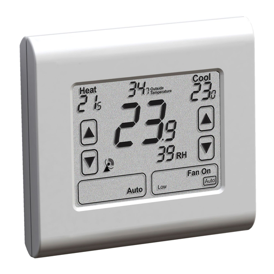
400 will use as room temperature. Room Humidity This indicates the current level or relative humidity within the room. The SMT-400 can simply display this value or, if set be the installer, take some action to increase or decrease room humidity. - Page 5 The SMT-400 has advanced energy saving functions such as door or window monitoring. (Optional door window switch required). If enabled by the installer, when a door or window is left open for longer than a few minutes the SMT-400 will display this text and may restrict user functions until the door or window is closed.
-
Page 6: Making Comfort Adjustments
SMT-400 off). If the SMT-400 has been shut down via this method the Text “Off” will flash. If you are at the SMT-400 you can simply touch the mode button to restart your heating and cooling once again. -
Page 7: Programming
If the SMT-400 is OFF, tapping the “FAN” button will turn the fan ON or OFF as desired. If your system has 3 fan speeds these can also be selected by tapping the “FAN” button. Programming Although your SMT-400 is not a traditional programmable thermostat it does provide a cloud based scheduling function via the Smart Temp Comfort App. - Page 8 Once you have your Smart Temp "Comfort App" account set up and paired with your SMT-400 you can permit others to also have Wi-Fi control of your SMT-400. For example, a SMT-400 may be installed in a home and can then invite other family members to join in controlling the same SMT-400 thermostat.
- Page 9 If after 2 minutes of power up the SMT-400 has not connected to a wi-fi router it disables the flashing wi-fi icon on the LCD (some people may not wish to use the SMT-400 Wi-fi function so the icon is disabled). If you wish to re-pair the SMT-400, simply press the location of the icon on the SMT-400 display for 5 seconds.
-
Page 10: Installation
Switch 1 – Relay Assignment The SMT-400 is fitted with 5 relays capable of switching up to 24VAC @ 1Amp. Switch 1 sets the function of these relays as either 3 fan speeds with 1 heat and 1 cool operation or single fan speed with 2 heat and 2 cool, in either HP (heat pump / reverse cycle) or HC (heat with add on cool) mode. -
Page 11: Typical Drawings
When the SMT-400 is set for Heat Pump mode (Sw2 is on) then this switch sets the reversing valve logic (O/B). When the SMT-400 is set for Heat Cool mode (Sw2 is off) then this switch sets the mode for the Heater Fan Logic (HG or HE mode). - Page 12 12 | P a g e SMT-400 Draft Manual...
- Page 13 13 | P a g e SMT-400 Draft Manual...
-
Page 14: Using Remote Temperature Sensors
Detailed information on the 8 DIP switches can be found on page 10 of this manual. Check the wiring matches that of the equipment the SMT-400 is to control and that all wiring is tight and not likely to short between adjacent wires. -
Page 15: Advanced Installer Settings
Check this sensor location. Advanced Installer Settings The SMT-400 is fitted with many advanced functions that can be finetuned by the installer to specifically match the needs of the user’s project. Normally these functions will not need to be altered from the factory default position however, there may be times when you wish to alter a setting or control capability so that the SMT-400 performance will perfectly match a particular application. - Page 16 400 has turned off. 8 Permitted Modes The SMT-400 operational modes can be set to set to suit the demands of the user or the limits of the heating and cooling system. Selecting the options below defines how the mode button operates 0 Off and Auto (Heat &...
- Page 17 9 Room and Set Temperature Display The SMT-400 operational modes can be set to set to suit the demands of the user or the limits of the heating and cooling system. Selecting the options below defines how the mode button operates 0 Shows both Room and Set Temperature.
- Page 18 2 If Fan On, Fan Mode will change to Auto and remain in Auto. Fan button will be hidden. 3 If Fan On, Fan mode will temporarily change to Auto and return fan on when SMT-400 is on. 4 If Fan On, Fan mode will temporarily change to Auto and return fan on when SMT-400 is on.
- Page 19 Assignable Relay Functions The SMT-400 has a volt free (2a @ 24V max) relay with changeover contacts that has a selection of functions. Some functions have a threshold that can be applied to them, installer adjusts this threshold value option number 23 (below).
- Page 20 0-10V Fan Minimum Voltage To prevent a fan motor potentially running too slowly, the SMT-400 permits you to set a minimum fan run voltage. This is the lowest voltage that will be applied to the fan when the fan is running.
- Page 21 Universal Input 2 Universal Input 3 The SMT-400 has 3 independent universal inputs. Each input has the same library of functions. A more detailed description of the universal input functions can be found on page 28 of this manual Input not used Remote Sensor –...
- Page 22 The SMT-400 can be set to automatically turn itself off in a predefined time after it has been turned on. If the SMT-400 is set to commercial mode, this is the time the SMT-400 will run for before automatically returning to setback mode.
- Page 23 Disabled (Default) Enabled To prevent excessive energy consumption when Wi-Fi is lost, the SMT-400 can be set to automatically turn off 30 minutes after Wi-Fi is lost. This function can also be enabled or disabled from the Smart Temp Comfort App.
-
Page 24: Control Logic
SMT-400 internal relays change. The equipment fan speed should change accordingly. Test Heating and Cooling (if both fitted) Turn the SMT-400 to Auto season mode (if available). To change mode tap the mode button until the words “Heat” and “Cool” are shown on the LCD. -
Page 25: Advanced Functions
ModBus Only. Duct sensor – when the SMT-400 is used to control a fan coil with two pipes, strapping a sensor to the fan coil pipe will permit the SMT-400 to automatically select the appropriate mode based on pipe temperature. -
Page 26: 0-10V Output Functions
Note. The SMT-400 will apply a 3-minute fixed timer between stages. CWP Output – The assignable relay will energise when the SMT-400 calls for heating or cooling even if the fault input is holding the equipment relays off (and 0-10V output at 0v). This function permits the SMT-400 to be used on water sourced heat pumps and to call for a water pump start if heating or cooling is needed even though the equipment outputs are held off. -
Page 27: Modbus Communications
When cooling is required and If the outside air temperature is at least 3c below the current room temperature then the SMT-400 will start Economy cycle cooling. The LCD will display the text “Fresh Air in Use”. If the indoor fan is in Auto Mode (Cyclic fan) and not running when the Economy Function is required, then the SMT-400 will automatically start the indoor fan. -
Page 28: High And Low Balance Points
SW2=ON (Heat Pump Mode), Installer menu 17 = option 1 E.Heat (Emergency Heat Mode) Set option 13 in the installer menu to the value that when the outside air temperature is below this value the SMT-400 will automatically switch to emergency heat mode when heating is required. - Page 29 Latched occupancy detection requires the use of two inputs in the SMT-400. Two separate inputs of the SMT-400 are used to test the traffic flow (are people entering or leaving the room). If people have entered the room the SMT-400 will remain latched into occupied mode regardless of whether the people move about or remain still.
-
Page 30: Specifications
White LED. Back Light Life 3,000 hours to half brightness. Communications Protocol ModBus RTU – contact Smart Temp for objects list. Fan Speeds Based on difference between room and set temp. WiFi FCC / CE approved 802.11b/g/n 2.412 – 2.48Ghz... -
Page 31: Troubleshooting
Set LBP with the LB=XX value in the installer menu, details manually selecting on page 22 The word OFF is This is not a fault. SMT-400 being held off Aux input set to remote OFF function. This input is holding flashing on the LCD. by external switch or device. - Page 32 Deg F mode as set in installer menu. Cannot select SMT-400 set for single fan speed. Turn the SMT-400 dip switch settings so that SW1 = ON. If multiple fan speeds. the Air Conditioning supports this function The SMT-400 may be receiving a signal Contact the building manager.
Need help?
Do you have a question about the SMT-400 and is the answer not in the manual?
Questions and answers