
Related Manuals for Acson A5WM


Summary of Contents for Acson A5WM
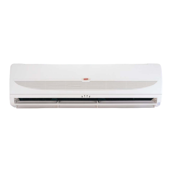
- Page 1 Models: AWM 07G/GR A5WM 07G/GR AWM 09G/GR A5WM 09G/GR AWM 10G/GR A5WM 10G/GR AWM 15G/GR A5WM 15G/GR A5WM 20G/GR A5WM 07G/GR A5WM 25G/GR A5WM 10G/GR A5WM 301/1R A5WM 15G/GR Wall Mounted Split Systems REGISTERED AWM - G - 2005 ISO 9002...
- Page 2 A : 220 - 240V/1Ph/50Hz Model Type R : Heatpump Omitted if Cooling Series G : G series Capacity 10 : 9,500 Btu/h Model Name WM : Wall Mounted Refrigerant 5 : R410A Omitted if R22 Brand A : ACSON...
-
Page 3: Model Name
A : 220 - 240V/1Ph/50Hz Model Type R : Heatpump Omitted if Cooling Only Series C : C series Capacity 10 : 9,500 Btu/h Model Name LC : Single Split Condensing Unit Refrigerant 5 : R410A Omitted if R22 Model Brand A : ACSON... - Page 4 Model Type R : Heatpump Omitted if Cooling Series B : B series C : C series Capacity 30 : 30,000 Btu/h Model Name LC : Single Split Condensing Unit Refrigerant 4 : R410A Omitted if R22 Brand A : ACSON...
-
Page 5: Quiet Operation
2. FEATURES EASY INSTALLATION The wall mounted fan coil unit is easily installed because of its compact size, slimness and light weight. Slim and short outdoor unit can be easily installed even in a narrow balcony and passageway and yet have a stable profile. -
Page 6: Self Diagnosis
HIGH EFFICIENCY HEAT EXCHANGER - The compact design of the 3-fold structure heat exchanger provides a large surface are for better and efficient heat exchange. The unique Hydrophilic slit fin has greatly improved the air flow and the contact surfaces with the air thus to boost the cooling capacity. - Page 7 INDOOR UNIT A5WM-G SERIES PRODUCT LINE UP CLASSIFICATIONS Handset Air Purification A5WM ACIBC ACNBC ACIBC ACNBC ACIBC ACNBC ACXBC ACIBC ACNBC ACXBC ACIBC ACNBC ACIBC ACNBC AFCA ACIBC 07GR ACNBC ACIBC 09GR ACNBC ACIBC 10GR ACNBC ACIBC 15GR ACNBC ACIBC...
- Page 8 OUTDOOR UNIT A5LC PRODUCT LINE UP CLASSIFICATIONS Refrigerant Safety Devices Special Grille Compressor Marking Others Ctrl + Fin A5LC ACPOE ACPOB ACPXB ACPOA ACPXA ACPOC ACPOC ACPOA 07CR ACPOE 10CR ACPOB 15CR ACPOA 20CR ACPOC 25CR ACPOC 28CR ACPOA...
-
Page 9: Temperature Setting
11. CONTROLLER G12 REMOTE CONTROLLER Temperature Setting Personalised Setting Press and hold the button for 3s to To set the desired room temperature, press the button to initiate personalized setting. increase or decrease the set Set the individual setting e.g. temperature. -
Page 10: Indicator Lights
INDICATOR LIGHTS AWM / A5WM - G SERIES IR signal receiver When there is infrared remote control operating signal, the signal receiver on indoor unit will made a (beep) for signal acceptance confirmation. Cooling unit / Heatpump unit LED Indicator Lights for Cooling Unit / Heatpump... - Page 11 AWM 301 / 301R , A5WM 311 / 301R LED Indicator Lights For Cooling Unit LED Indicator Lights : Normal Operation And Fault Conditions For Cooling Unit Operation / Fault Indication Action Power Timer Sleep Timer on Sleep mode on...
- Page 12 LED Indicator Lights For Heatpump Unit Cooling mode Dry mode Heat/Fan mode Sleep mode (red/green) LED Indicator Lights : Normal Operation And Fault Conditions For Cooling Unit Normal Operation / Fault Indication Action Cool Heat Sleep Cooling mode Dry mode Fan mode Heat mode Auto mode in heating operation...
-
Page 13: Controller Specifications
CONTROLLER SPECIFICATIONS (A) 3 HOT SYSTEM (HEATING CYCLE) a) Hot start At the beginning of heating operation (cold start, after defrosting or thermostat resumes operation) the indoor fan operation is controlled in accordance with the temperature of the indoor heat exchanger to send warm air from the start. - Page 14 Hot Keep (Apply to AWM-GR) After thermostat cut out, the indoor fan operation is controlled in accordance with the indoor heat exchanger temperature to utilize the extra heat and preserve indoor comfort. The indoor fan can be switched to ON, OFF by setting the slide switch shown in the diagram. This slide switch is located at the front frame cover.
- Page 15 (B) TURBO MODE (APPLY TO AWM-GR) TURBO function is available in COOL, HEAT and DRY modes only. When TURBO function is set, working temperature for cooling cycle is decreased by 2 C, working temperature for heating cycle is increased by 2 The indoor fan will force to HIGH fan.
- Page 16 (E) FROST PREVENTION AND FILTER CHECK In order to prevent the freezing of indoor coil, the controller will operate as follow. (F) AUTO RANDOM RESTART When power resumed, the unit will automatically restart and operate at the previous setting as before power failure occurred.
-
Page 17: Servicing And Maintenance
13. SERVICING AND MAINTENANCE Off the unit Unscrew the air discharge housing Flip open the air discharge housing Clean the blower Close the air discharge housing and tighten it with screw The unit is designed to give a long life operation with minimum maintenance required. However, it should be regularly checked and the following items should be given due attention. -
Page 18: Troubleshooting
14. TROUBLESHOOTING When a malfunction of the air conditioner unit is detected, immediately switch off the main power supply before proceeding with the following troubleshooting procedures. The following are common fault conditions and simple troubleshooting tips. If any other fault conditions which are not listed occur, contact your nearest local dealer. -
Page 19: Exploded View And Parts List
15. EXPLODED VIEW AND PARTS LIST INDOOR UNIT MODEL: A5WM / AWM 07G / 07GR / 09G / 09GR / 10G / 10GR / 15G / 15GR... - Page 20 A5WM / AWM 07G / 09G / 10G / 15G No Descriptions Part No No Descriptions Part No Assy., Chassis Air Discharge Housing A5WM / AWM 07/09G A50124064147 A5WM / AWM 07/09G A50124062325 A5WM / AWM 10/15G A5WM / AWM 10/15G...
- Page 21 MODEL: A5WM / AWM 20G / 20GR / 25G / 25GR...
- Page 22 MODEL : A5WM / AWM 20G / 25G No Descriptions Part No No Descriptions Part No Assy., Chassis A50124068170 Assy., Control Box A50044071955 Fan, Motor Assy., Control Box Cover A50124071418 AWM 20G Assy., Front Cover A50124071425 A03034074205 AWM 25G Air Discharge Housing...
- Page 23 MODEL: AWM 301 / 301R, A5WM 311 / 301R...
- Page 24 MODEL : A5WM 311 / AWM 301 No Description Part No No Description Part No ASSY, INSTALLATION BRACKET A50014050721 ASSY, CONTROL BOX A50044052607 ASSY. CHASSIS A50124050703 LED LIGHT BRACKET A12014050679 PIPING CLAMP A07014024546 G12 HANDSET A04084065328 FAN BUSH BRACKET A12014050709...
- Page 25 OUTDOOR UNIT MODEL: A5LC 07C No Descriptions Part No No Descriptions Part No Assy., Base Pan A50014057372 10 Left Panel A01014052510 Assy., Condenser Coil A50024064720 11 Right Panel A01014052509 Valve Bracket A01014051164 12 Assy. Control Panel A50044054806 Compressor A04019019592 13 Assy., Front Panel A01014052512 Assy., Partition A50064065275...
- Page 26 MODEL: A5LC 10C / 15C No Descriptions Part No No Descriptions Part No Assy., Base Pan A50014051158 11 Right Panel A01014051167 Assy., Condenser Coil A50024064721 12 Assy., Front Panel A01014051171 Valve Bracket A01014051164 13 Assy. Control Panel Compressor A5LC 10C A50044058195 A5LC 10C A04019019590...
- Page 27 MODEL: A5LC 07CR No. Descriptions Part No No. Descriptions Part No Assy., Base Pan A50014057372 12 Right Panel A01014052509 Assy., Condenser Coil A50024064720 13 Assy. Control Panel A50044059032 Valve Bracket A01014051164 14 Assy., Front Panel A01014052512 Compressor A04019019592 15 Assy., Valve Cover A50124055172 Assy., Partition A50064065275...
- Page 28 MODEL: A5LC 10CR / 15CR No. Descriptions Part No No. Descriptions Part No Assy., Base Pan A50014051158 11 Left Panel A01014051166 Assy., Condenser Coil 12 Right Panel A01014051167 A5LC 10CR A50024064721 13 Assy., Front Panel A01014051171 A5LC 15CR A50024066517 14 Assy. Control Panel Valve Bracket A01014051164 A5LC 10CR...
- Page 29 MODEL: ALC 18C, A5LC / ALC 20C No. Descriptions Part No No. Descriptions Part No Assy. Base Pan Compressor ALC 18C A50014077978 ALC 18C A50049022614 A5LC/ALC 20C A50014013884 ALC 20C A04019018334 Assy. Outdoor Coil A5LC 20C A04019021361 ALC 18C A50024077968 Front Panel, Left A01014070597 ALC 20C...
- Page 30 MODEL: A5LC / ALC 25C, A5LC / ALC 28C No. Descriptions Part No No. Descriptions Part No Front Panel, Left A01014070947 Assy. Base Pan A50014073884 Service Panel A01014070949 Assy. Outdoor Coil Terminal Cover Panel A01014070838 ALC 25C/28C A50024070959 Assy. Control Panel A5LC 25C/28C A50024079238 A5LC/ALC 25C...
- Page 31 MODEL: A5LC / ALC 20CR No. Descriptions Part No No. Descriptions Part No Front Panel, Left A01014070597 Assy. Base Pan A50014073884 Service Panel A01014070598 Assy. Outdoor Coil Terminal Cover Panel A01014070838 ALC 20CR A50024077089 Assy. Control Panel A5LC 20CR A50024075143 ALC 20CR A50044077198 Motor Bracket...
- Page 32 MODEL: A5LC / ALC 25CR, A5LC / ALC 28CR No. Descriptions Part No No. Descriptions Part No Front Panel, Left A01014070947 Assy. Base Pan A50014073884 Service Panel A01014070949 Assy. Outdoor Coil Terminal Cover Panel A01014070838 ALC 25CR/28CR A50024077092 Assy. Control Panel A5LC 25CR/28CR A50024075147 A5LC/ALC 25CR...
Need help?
Do you have a question about the A5WM and is the answer not in the manual?
Questions and answers