Table of Contents
Advertisement
Quick Links
Advertisement
Table of Contents

Related Manuals for Contex Chroma 8040


Summary of Contents for Contex Chroma 8040
- Page 1 CHROMA 8040, 6040, 3040 Wide Format Color Scanner Operator’s Guide...
- Page 2 Contex A/S reserves the right to modify the information given in this publication without prior notice. The Contex scanner products are covered by one or more of the following patents: 5.117.295, 5.377.020, 5.502.578, 5.640.465, 5.642.207 other patents pending in the US and elsewhere.
- Page 3 Preface The CHROMA Wide Format Color Scanners provide complete solutions for scanning drawings, maps and pictures for use with Color reproduction, Color Copying, CAD, GIS, DTP and Archival programs. The built-in dedicated Color feature extraction hardware and high- speed Digital Image Processing (DIP) does image processing and enhancement in real time.
-
Page 4: Table Of Contents
Table of Contents 1. Introduction 2. CHROMA System Overview 2.1 Software 3. Operating Modes 3.1 RGB mode 3.2 Indexed color mode 3.3 Feature extraction (classified) color mode 3.4 Graytone mode 3.5 B/W modes 3.6 B/W Copy Modes 3.7 2D-Sharpening, 2D-Softening and 2D-Blur 3.8 Resolutions, Pixel Distance and Scanwidth 4. - Page 5 8. Appendix A: CHROMA specifications 9. Appendix B: Regulations 9.1 FCC Regulations 9.2 EC Regulations 10. Appendix C: Program License Agreement 10-1 11. Appendix D: Important Safety Instructions 11-1 12. Appendix E: Index 12-1...
-
Page 7: Introduction
Introduction 1. Introduction The Contex CHROMA Wide Format Color Scanners are cost effective solutions for large format, high volume color scanning. This guide applies to the following models: • FSC8040 CHROMA Wide Format Color Scanner scans originals up to 40” Scan Width, and up to 800dpi resolution. ADL+ and 2D- Sharpen and Soften filters •... - Page 8 Introduction The CHROMA Color Scanners are designed to work with many types of scanning applications: • Reproduction (Large Format Color Copying) Join the CHROMA Color Scanner with a large format ink-jet printer to form an ideal large format digital color copier, handling large color posters, color drawings, maps, photos and fine art.
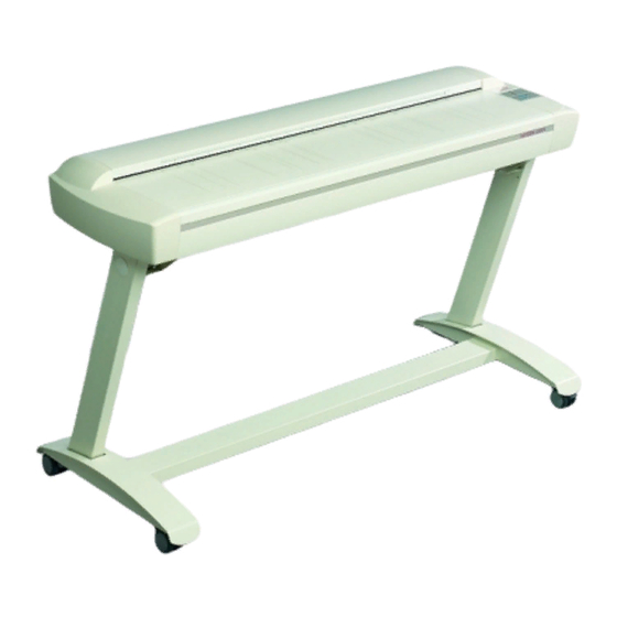
- Page 9 Introduction Figure 1-1 The CHROMA Large Format Color Scanner...
-
Page 10: Chroma System Overview
System Overview 2. CHROMA System Overview The CHROMA Wide Format Color Scanners, incorporate three 5350 RGB-triplet pixels, tri-linear color CCD cameras (21.400 RGB-triplets), and have color balanced stabilized fluorescent lighting and individual adaptive light compensation on each pixel. There are three CHROMA models and they include the following features: •... - Page 11 System Overview • The CHROMA scans media of up to 0.6 inch (15mm) thick and thus supports originals mounted on cardboard, foamboard, gatorboard etc. • All digital cameras provide superior point-of-origin color capture for low noise and extended dynamic range. •...
- Page 12 System Overview INKJET PC or WORKSTATION CHROMA COLOR SCANNER PRINTER/ PLOTTER Large format full color Scanning /Image Enhancement output/copying to ink-jet Color Feature Extraction plotter supported by Conversion, De-speckling, De-skewing, Rotation & Alignment Viewing and Zooming third party software RIPS File Formats: (more than 50 selectable including color formats:...
-
Page 13: Software
JETimage copy software is available in two editions: JETimage BASE and JETimage PRO. The application is designed to interface your Contex Scanner with a wide range of popular printers for large format copying. JETimage is a powerful, professional tool enabling easy production of vivid high... - Page 14 System Overview monchrome enhancement features for demanding black and white copy assignments. JETimage can come with both touch-screen and conventional mouse-keyboard interfacing. The PRO edition enables Copy-to-File and Print-From-File features, accounting, Paneling and Nesting. WIDEcapture for Photoshop Wide Format Scanning Software for Macintosh and Windows as a Plug-in for Adobe Photoshop.
-
Page 15: Operating Modes
Operating Modes 3. Operating Modes The CHROMA Color Scanners work in six operating modes: • 24 bit RGB color mode • 8-bit indexed color mode • 8-bit feature extraction color mode • Graytone mode (256 graytones) • B/W modes (bitmapped, 2-level and 2D-adaptive) •... -
Page 16: Graytone Mode
Operating Modes 3.4 Graytone mode In Graytone mode, the actual graylevel of each pixel is scanned; 256 levels are recognized, corresponding to 1 byte (8 bits) per pixel. This results in graytone files that are 8 times larger than uncompressed files scanned in Line mode at the same resolution;... -
Page 17: Sharpening, 2D-Softening And 2D-Blur
Operating Modes 3.7 2D-Sharpening, 2D-Softening and 2D-Blur Through the WIDEimage and JETimage applications, you can manually set and control sharpening, softening and blurring filters, giving you rich possibilities for combining effects to obtain perfect enhancement results. For example, you may have an image with details (such as text or lines) you wish to sharpen. - Page 18 Operating Modes Scan-width Scan Width is also set from WIDEimage. Use the units of the ruler printed near the original’s insertion slot on the CHROMA Scanner to determine the value. The user can select through WIDEimage the preferable insertion method for the original. Either side aligned loading or centered loading can be selected.
-
Page 19: Operator Panel And Indicators
Operator Panel and Indicators 4. Operator Panel and Indicators The CHROMA Color Scanner Operator Panel layout shown overleaf is divided into two keys and four indicators. The two operating keys are positioned at the bottom: The Paper Reverse key (C), and the Paper Feed/Forward key (A) with a Ready indicator (B) attached. -
Page 20: Power On Indicator
Operator Panel and Indicators 4.3 Power On Indicator Lights when the scanner is ON and is receiving power. 4.4 Wait Indicator (Warm Up) Lights when the scanner power is turned on, and stays on during the internal diagnostic and stabilization phase. Keyboard input is prevented during this time. - Page 21 Operator Panel and Indicators Figure 4-1 Operator Panel...
-
Page 22: Original's Insertion Slot
Original’s Insertion Slot 5. Original’s Insertion Slot 5.1 Rulers The Original’s insertion slot shown below is marked with a measurement ruler on top. The ruler can be slid out and flipped over to select/change your preferred measurement units – inches or millimeters. -
Page 23: Scanning Thick Media
Original’s Insertion Slot The following table shows some of the most common drawing widths and the corresponding scan-width settings in inches, mm and scanner units: Scanner Original Drawing Width*: Units Minimum media size of scanner 6.0"/152mm Minimum Scan Width (A5) 6.0"/152mm A-Size (letter) and approx. - Page 24 Original’s Insertion Slot fit the slot to the thickness of your original. This feature adds an extra dimension to scanning possibilities. To change the insertion slot space, open the Original’s Insertion Slot cover and slide the media thickness adjustments found at each side to the same setting.
- Page 25 Original’s Insertion Slot The Normal position (Step 0: 2mm/0.08”) is detected by a sensor in the scanner. Auto-adjustment of the scanner’s light profile, stitching etc. only takes place in the Normal position. With extended media thickness positions, the last performed auto-adjustment is stored and utilized.
-
Page 26: Removing The Original Pressure Platen
Original’s Insertion Slot 5.3 Removing the Original Pressure Platen To remove the original pressure platen fixture when cleaning the scanning area, press down the platen fixture while sliding the left and right extended media thickness adjustment sliders fully towards the middle of the platen. - Page 27 Original’s Insertion Slot A small locking pin will keep the slider in the exit position to facilitate removal and insertion of the pressure platen.
-
Page 28: Installation
Installation 6. Installation 6.1 Set up the scan station Your Wide Format Scanner should be placed either on a sturdy table or the specially designed stand-alone floor stand. The specially designed floor-stand is required for mounting the optional Copy Kit (PC and Screen holders). -
Page 29: Connection Through The Scsi Interface
However for best performance, we strongly recommend that you use the board and driver delivered with the Contex Interface Kit. Regulatory Notice: This product has been tested to comply with the EMC Standards EN55022 and FCC, Part 15. -
Page 30: Step 1: Install The Scsi Host Adapter Board
Installation 5. Set scanner DIL switch 4 termination properties. 6.4.1 Step 1: Install the SCSI host adapter board 1. Set the PC-system unit power-switch to OFF. 2. Set any external device power switches to OFF (such as printers, displays etc.). 3. -
Page 31: Step 4: Set The Scanner Dil-Switches
Installation 6.4.4 Step 4: Set the scanner DIL-switches The DIL-switches are used for setting up of the scanner’s SCSI connection ports, and for selection of the scanner test mode and the scanner forced boot start up mode. The DIL-switches are set from the factory to default settings that apply to most common configurations so usually you will not have to change them. - Page 32 Installation You will find the DIL-switches in the small Smart Card drawer labeled “PUSH” behind the scanner front streamer. To access the switches remove the streamer, push the drawer inwards and release so it pops open and remove the Smart Card. Figure 6-1 Access the DIL-switches Important: Remember to reinsert the Smart Card when finished setting the DIL-switches and before turning power on.
- Page 33 Installation Device number setup – switch 1,2,3 Make sure the power to the computer and the scanner are OFF when setting the SCSI device number, as the switch settings are only read from the scanner DIL-switch during the scanner’s power up. You can set up the SCSI device no.
- Page 34 Installation The following 3 scenarios show how to terminate the SCSI bus correctly: A. The Scanner is the only external device on the SCSI bus Switch 4 must be ON SCSI SCANNER Host Computer B. The Scanner is the last device on the SCSI bus Switch 4 must be ON SCSI SCSI...
-
Page 35: Installation Verification
Installation Troubleshooting and Test Controls – switches 5, 6, 7 and 8 Switch 5. SCAN-SCSI (SCSI connectors 0A & 0B) - No synchronous transfer: Disables SCAN-SCSI synchronous transfer mode (reverts to asynchronous transfer). Only use this mode for testing as it slows down the scanner. -
Page 36: Preliminary Maintenance
Installation perform a simple scan by hitting the Scan button (WIDEimage) or Copy button (Jetimage). 6.6 Preliminary Maintenance Once you have setup your scanner and verified your installation, it is important that you run your first maintenance session before working with the scanner. -
Page 37: Maintenance
Maintenance 7. Maintenance Regular scanner maintenance is a sure way to minimize costly downtime. The three routine maintenance procedures cleaning, camera alignment and calibration will improve image quality and reduce your service costs. The three functions are closely entwined and they should all be performed in a maintenance session, starting with cleaning the scan area and ending with calibration. - Page 38 Maintenance Remove the pressure platen. Press down on the platen as you pull the left and right sliders towards the scanner’s center until the metal safety buttons on each side of the scanner, pop up. Use the two handles to lift out the pressure platen as soon as you feel the sliders disengage.
- Page 39 Maintenance Replace the pressure platen. Lift the pressure platen into its original position. Press down on the metal safety buttons to let the two sliders move back and lock the platen into place. Close the scanner cover. Keep out dust and reduce maintenance time. Cover your scanner with the plastic dust cover when not in use.
-
Page 40: Camera Alignment
Maintenance 7.2 Camera Alignment Height alignment and stitching Camera alignment tools: Adjustment Chart, 3C-Kit Screwdriver, Scanner Maintenance Software The Scanner should be warm. Make sure that the scanner has been turned on for at least one hour prior to camera alignment. Slight light intensity changes and camera shifting can occur just after turning the scanner on and the warm-up time will ensure that light conditions and camera heights have stabilized. - Page 41 Maintenance Start the Scanner Maintenance Utility. Select Programs > Scanner Maintenance to start the Maintenance Wizard. wizard will guide you through Camera Alignment, Stitching and Calibration. Click the Next button in the welcoming dialog to proceed with Camera Alignment. Insert the Maintenance Sheet. The sheet’s printed side must be inserted face down.
- Page 42 Maintenance Use the arrow indicators to adjust the camera. The wizard shows you how to adjust the current camera. The arrow on the left shows you which direction to turn the screw with your screwdriver. Red arrows indicate that you are far from your target and can make large turns of the screw.
-
Page 43: Calibrate The Scanner
Maintenance 7.3 Calibrate the Scanner Basic and color calibration Calibration tools: Maintenance Sheet Clean the scanning area and align the camera. Before you calibrate, make sure that you have gone through the first two C’s of maintenance – Cleaning the scan area and Camera Alignment. -
Page 44: Camera Out Of Light Error
Maintenance Calibration Press the wizard’s Next button to start the Basic Calibration process. Color Calibration follows immediately after. The wizard will inform you when Calibration is complete and instruct you to remove the Maintenance Sheet. Wrapping up. Calibration completes the maintenance process. Remove the Maintenance Sheet from the scanner. - Page 45 Maintenance Camera C: 3 flashes per period. Before proceeding with CCD camera height adjustment, perform the following for the camera that has the out of light error: 1. Turn the height adjustment screw eight turns clockwise. 2. Turn the scanner power off, and then on. If the error still shows, turn the height adjustment screw sixteen turns counterclockwise.
-
Page 46: Appendix A: Chroma Specifications
A: Specifications 8. Appendix A: CHROMA specifications CHROMA X040 Models 3040 6040 8040 Maximum Resolution (dpi): Variable resolution setting: from 50 dpi in one dpi increments 1.3 “/s 1.7”/s 2.5”/s Scan Speed: 400dpi Turbo, 24 bit RGB scans Digital Image Processing: Dual 2D-Adaptive enhancement processing. -
Page 47: Appendix B: Regulations
B: Regulations 9. Appendix B: Regulations 9.1 FCC Regulations This equipment has been tested and found to comply with the limits for a class A digital device, pursuant to Part 15 of the FCC Rules. These limits are designed to provide reasonable protection against harmful interference when the equipment is operated in a commercial environment. -
Page 48: Ec Regulations
B: Regulations 9.2 EC Regulations... - Page 49 B: Regulations Supplementary Information Warning This is a class A product. I a domestic environment this product may cause radio interference in which case the user may be required to take adequate measures.
-
Page 50: Limited Warranty
The replacement of any diskette not meeting the Contex "Limited Warranty" and which is returned to Contex or an authorized Contex dealer with a copy of your receipt, or If Contex or the dealer is unable to deliver a replacement diskette which is free of defects in materials or workmanship, you may terminate this Agreement by returning the program and your money will be refunded. - Page 51 10-2 C: License In no event will Contex be liable to you for any damages including any lost profits, lost savings, or other incidental or consequential damages arising out of the use or inability to use such program, even if Contex or an authorized Contex dealer has been advised of the possiblity of such damages, or for any claim by any other party.
-
Page 52: Appendix D: Important Safety Instructions
D: Safety 11-1 11. Appendix D: Important Safety Instructions Read all of these instructions and save instructions for later use. Follow all warnings and instructions marked on the scanner. A. Do not place the scanner on an unstable surface, stand, cart or table. - Page 53 11-2 D: Safety I. Do not attempt to service the scanner yourself. Opening or removing those covers requiring tools may expose you to dangerous voltage points or other risks. Refer all servicing in those compartments to authorized service personnel. J. Unplug the scanner from the wall outlet and refer servicing to authorized service personnel under the following conditions: •...
-
Page 54: Appendix E: Index
E: Index 12-1 12. Appendix E: Index Aerosol cleaners....11-1 Power source ......11-1 CAD......... 3-3 Pressure Platen....... 5-6 Camera out of Light error ..7-10 Program License Agreement. 10-1 Computer Aided Design ..3-3 Ready indicator ....... 4-1 Device number ......6-4 Resolution......
Need help?
Do you have a question about the Chroma 8040 and is the answer not in the manual?
Questions and answers