Table of Contents
Advertisement
Quick Links
Advertisement
Table of Contents

Subscribe to Our Youtube Channel
Related Manuals for KT&C Omni960-4


Summary of Contents for KT&C Omni960-4
- Page 1 Digital Video Recorder Omni960-4 Omni960-8 Omni960-16 Omni960-32 User Manual...
- Page 2 User Manual OMNI960 Digital Video Recorders Regulatory information FCC information compliance: This equipment has been tested and found to comply with the limits for a digital device, pursuant to part 15 of the FCC Rules. These limits are designed to provide reasonable protection against harmful interference when the equipment is operated in a commercial environment.
- Page 3 User Manual OMNI960 Digital Video Recorders Thank you for purchasing our product. If there is any question or request, please do not hesitate to contact your dealer. KT&C Certified Dealers can contact KT&C directly. This manual is applicable to the OMNI960 Series digital video recorders. This manual may contain inadvertent technical discrepancies or printing errors;...
-
Page 4: Preventive And Cautionary Tips
User Manual OMNI960 Digital Video Recorders Preventive and Cautionary Tips Before connecting and operating your device, please be advised of the following information: • Ensure that the unit is installed in a well-ventilated, dust-free environment. • These units are designed for indoor use only. •... -
Page 5: Product Key Features
HDD Management 1 SATA hard disk can be installed in the OMNI960-4 models, 2 SATA hard disks in the OMNI960-8 & OMNI960-16 models, and up to 4 SATA hard disks in the OMNI960-32; with a maximum of 4TB storage capacity for each disk. One eSATA on OMNI960-32. - Page 6 Operation, exceptions and log recording and searching. Import and export of device configuration information. Network Functions 1 self-adaptive 10M/100M network interface for OMNI960-4/8/16, and 1 self-adaptive 10M/100M/1000M network interface for OMNI960-32 models. IPv6 is supported. TCP/IP protocol, PPPoE, DHCP, DNS, DDNS, RTSP, NTP, SADP, SMTP, SNMP, UPnP™, NFS, and iSCSI are supported.
- Page 7 User Manual OMNI960 Digital Video Recorders Remote parameters setup; remote import/export of device parameters. Remote viewing of the device status, system logs and alarm status. Remote locking and unlocking of control panel and mouse. Remote HDD formatting and program upgrading. ...
-
Page 8: Table Of Contents
User Manual OMNI960 Digital Video Recorders TABLE OF CONTENTS Product Key Features ...................... 4 C H A P T E R 1 ................Error! Bookmark not defined. Introduction ..........................11 1.1 Front Panel ....................... 12 1.2 IR Remote Control Operations ................15 1.3 USB Mouse Operation ..................... - Page 9 User Manual OMNI960 Digital Video Recorders 5.6 Configuring Holiday Record ................... 60 5.7 Configuring Redundant Record ................62 5.8 Configuring HDD Group for Record ..............64 5.9 Files Protection ......................65 C H A P T E R 6 ................Error! Bookmark not defined. Playback ..........................
- Page 10 User Manual OMNI960 Digital Video Recorders 9.2.7 Configuring Multicast ................... 127 9.2.8 Configuring RTSP ..................127 9.2.9 Configuring Server and HTTP Ports ............. 128 9.2.10 Configuring Email ..................128 9.3 Checking Network Traffic ..................131 9.4 Network Detection ....................132 9.4.1 Testing Network Delay and Packet Loss ............
- Page 11 User Manual OMNI960 Digital Video Recorders 13.1 Configuring General Settings ................167 13.2 Configuring RS-232 Serial Port ................167 13.3 Configuring DST Settings ..................169 13.4 Configuring More Settings .................. 170 13.5 Managing User Accounts ..................171 13.5.1 Adding a User ..................... 171 13.5.2 Deleting a User ....................
-
Page 12: Chapter 1
User Manual OMNI960 Digital Video Recorders Chapter 1 Introduction... -
Page 13: Front Panel
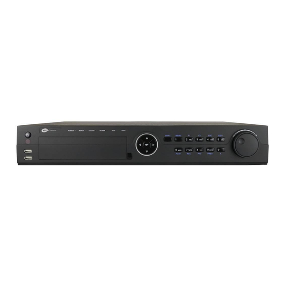
User Manual OMNI960 Digital Video Recorders 1.1 Front Panel OMNI960-4/8/16: The front panel of OMNI960-4/8/16 series DVR is shown below: Figure 1.1 Front Panel of OMNI960-4/8/16 Table 1.1 Description of Control Panel Buttons Name Function Description POWER indicator turns green when DVR is powered up. - Page 14 User Manual OMNI960 Digital Video Recorders OMNI960-32: The front panel of OMNI960-32 is shown below: Figure 1.2 Front Panel of OMNI960-32 Table 1.2 Description of Control Panel Buttons No. Name Function Description POWER Power on/off switch. ON/OFF USB Interface Connect to USB mouse or USB flash memory. IR Receiver Receiver for IR remote control POWER...
- Page 15 User Manual OMNI960 Digital Video Recorders Enter numeral “1”; 1/MENU Access the main menu interface. Enter numeral “2”; Enter letters “ABC”; The F1 button can be used to select all items on the list; 2ABC/F1 In PTZ Control mode, the F1 button can be used to zoom out (zoom-) the PTZ camera;...
-
Page 16: Ir Remote Control Operations
User Manual OMNI960 Digital Video Recorders 1.2 IR Remote Control Functions The device may also be controlled with the included IR remote control, shown in Figure 1.3. Note: Batteries (2×AAA) must be installed before operation. Figure 1.3 Remote Control Table 1.3 Description of the IR Remote Control Button Functions Name Description POWER... - Page 17 User Manual OMNI960 Digital Video Recorders Name Description PLAY Button Entering the All-day Playback menu. INFO Button Reserved. Selecting all items on the list; VOIP/MON Button In live view or playback mode, it can be used to switch between main and auxiliary video output.
-
Page 18: Usb Mouse Operation
User Manual OMNI960 Digital Video Recorders 1.3 USB Mouse Operation A regular 3-button (Left/Right/Scroll-wheel) USB mouse can also be used with this device. To use a USB mouse: 1. Plug USB mouse into one of the USB interfaces on the front panel of the device. 2. -
Page 19: Rear Panel
Omni960-4: Figure 1.5 Rear Panel OMNI960-4 Omni960-8 Figure 1.6 Rear Panel of OMNI960-8 OMNI960-16 Figure 1.7 Rear Panel of OMNI960-16 Table 1.6 Description of OMNI960-4/8/16 Rear Panel Item Description VIDEO IN BNC connector for analog video input. VIDEO OUT BNC connector for video output. - Page 20 User Manual OMNI960 Digital Video Recorders DB15 connector for VGA output. Display local video output and menu. AUDIO IN RCA connector for audio input. AUDIO OUT RCA connector for audio output. LAN Interface RJ45 10M/100M Ethernet interface. RS-485 Interface Connector for RS-485 devices. Connect the D+ and D- terminals to T+ and T- of PTZ receiver respectively.
-
Page 21: Starting Up And Shutting Down The Dvr
User Manual OMNI960 Digital Video Recorders terminals should be connected with the D+ and D- terminals of the next DVR. Alarm In/Out Connector for alarm input/output. eSATA Connects external SATA HDD, DVD-R/W. Ground(needs to be connected when DVR starts up) 100~240VAC 100~240VAC power supply. - Page 22 User Manual OMNI960 Digital Video Recorders Figure 1.11 Message Box for Power Off 4. Turn off the power switch on the rear panel of DVR. Rebooting the device In the Shutdown menu (Figure 1.9), you can also click Reboot to reboot the device.
-
Page 23: Chapter 2
User Manual OMNI960 Digital Video Recorders Chapter 2 Getting Started... - Page 24 User Manual OMNI960 Digital Video Recorders The Setup Wizard can walk you through some important settings of the device. By default, the Setup Wizard starts once the device has loaded. Operating the Setup Wizard: Select the system resolution from the drop-down menu. The default resolution is 1280×1024/60Hz. Click Apply to save the resolution settings.
- Page 25 User Manual OMNI960 Digital Video Recorders Figure 2.3 Login Window Click the Next button to enter the Date and Time settings window, as shown in Figure 2.4. Set the time zone, date format, system date and system time. Figure 2.4 Date and Time Settings Click Next button which takes you back to the Network Setup Wizard window, as shown in Figure 2.5.
- Page 26 User Manual OMNI960 Digital Video Recorders Figure 2.5 Network Configuration Note: The OMNI960-4/8/16 models provide one 10M/100Mbps self-adaptive network interface, the OMNI960-32 models provide one 10M/100M/1000Mbps self-adaptive network interface. Click Next button to enter the HDD Management window, shown in Figure 2.6.
- Page 27 User Manual OMNI960 Digital Video Recorders Figure 2.7 Record Settings Click Copy to copy the record settings of the current camera to other camera (s) if needed, as shown in Figure 2.8. Figure 2.8 Copy Record Settings Click OK to return to the Record Settings window. Click OK to complete the startup Setup Wizard.
-
Page 28: Chapter 3
User Manual OMNI960 Digital Video Recorders Chapter 3 Live View... -
Page 29: Introduction Of Live View
User Manual OMNI960 Digital Video Recorders 3.1 Introduction to Live View Live view shows you the video image getting from each camera in real time. The device automatically enters Live View mode when powered on. It is also at the very top of the menu hierarchy, thus pressing the ESC many times (depending on which menu you’re on) brings you to the Live View mode. -
Page 30: Operations In Live View Mode
User Manual OMNI960 Digital Video Recorders 3.2 Operations in Live View Mode In live view mode, the following functions can be realized: • Single Screen: showing only one screen on the monitor. • Multi-screen: showing multiple screens on the monitor simultaneously. •... -
Page 31: Using An Auxiliary Monitor
User Manual OMNI960 Digital Video Recorders Figure 3.1 Right-click Menu Table 3.3 Mouse Operation in Live View Name Description Menu Enter the main system menu by left-clicking the mouse on this choice Single Screen Switch to the single full screen by choosing channel number from the dropdown list. Multi-screen Adjust the screen layout by choosing from the dropdown list. -
Page 32: Main/Aux Output Switching
User Manual OMNI960 Digital Video Recorders • Previous Screen: Switch to the previous screen. • Next Screen: Switch to the next screen. • Quick Set: Set the video output mode to Standard, Bright, Gentle or Vivid. • Menu Output Mode: Select the menu output mode to HDMI/VGA, Main CVBS or Auto. •... - Page 33 User Manual OMNI960 Digital Video Recorders Enable Manual Instant Playback Mute/Audio on Record PTZ Control Digital Zoom Image Settings Close Instant Playback Instant Playback only shows the record in last five minutes. If no record is found, it means there is no record during the last five minutes.
- Page 34 User Manual OMNI960 Digital Video Recorders Figure 3.5 Image Settings Adjust the image parameters including the brightness, contrast, saturation, hue, sharpness level and noise reduction level by moving the sliding bar or increasing/decreasing the value. Note: The adjustable value range is 0~255 for the brightness, contrast, saturation and hue, 0~15 for the sharpness level and 0~5 for the denoising level.
-
Page 35: Configuring Live View Settings
User Manual OMNI960 Digital Video Recorders 3.3 Configuring Live View Settings Purpose: Live View settings can be customized according to different needs. You can configure the output interface, dwell time for screen to be shown, mute or turning on the audio, the screen number for each channel, etc. Steps: 1. - Page 36 User Manual OMNI960 Digital Video Recorders 2. Setting Camera Order Figure 3.8 Live View- Camera Order To set the camera order: Click the View tab to enter the camera order settings interface. Select an output interface and select a screen layout. Click to select a screen in the right region and double-click to select a channel in the left region.
-
Page 37: Channel-Zero Encoding
User Manual OMNI960 Digital Video Recorders 3.4 Channel-zero Encoding Purpose: Sometimes you need to get a remote view of many channels in real time from web browser or CMS (Central Management System) client software, in order to conserve bandwidth while still displaying multiple camera views, channel-zero encoding may provide the solution. -
Page 38: User Logout
User Manual OMNI960 Digital Video Recorders 3.5 User Logout Purpose: After logging out, the monitor turns to the live view mode and if you want to do some operation, you need to enter user name and password to log in again. Steps: 1. -
Page 39: Chapter 4
User Manual OMNI960 Digital Video Recorders Chapter 4 PTZ Controls... -
Page 40: Configuring Ptz Settings
User Manual OMNI960 Digital Video Recorders 4.1 Configuring PTZ Settings Purpose: Follow the procedure to set the parameters for PTZ. The configuring of the PTZ parameters should be done before you control the PTZ camera. Before you start: Check that the PTZ and the DVR are connected properly through the RS-485 interface. Steps: 1. -
Page 41: Calling Presets
User Manual OMNI960 Digital Video Recorders Figure 4.2 PTZ- More Settings 2. Use the directional button to wheel the camera to the location where you want to set preset. 3. Click the round icon before Save Preset. 4. Click the preset number to save the preset. Repeat the steps2-4 to save more presets. -
Page 42: Customizing Patrols
User Manual OMNI960 Digital Video Recorders Figure 4.4 PTZ- Call Preset 3. Choose the preset number. Call preset in live view mode: Steps: 1. Click the PTZ Control icon in the quick setting bar to enter the PTZ setting menu in live view mode. - Page 43 User Manual OMNI960 Digital Video Recorders moving on to the next key point. The key points are corresponding to the presets. The presets can be set following the steps above in Customizing Presets. Steps: 1. Enter the PTZ Control interface. Menu>Camera>PTZ>More Settings 2.
-
Page 44: Calling Patrols
User Manual OMNI960 Digital Video Recorders Figure 4.8 KeyPoints Deletion 4.2.4 Calling Patrols Purpose: Calling a patrol makes the PTZ to move according the predefined patrol path. Call patrol in the PTZ setting interface: Steps: 1. In the PTZ setting interface. Menu>... -
Page 45: Customizing Patterns
User Manual OMNI960 Digital Video Recorders 1. Press PTZ control on the IR remote, or click PTZ Control icon on the quick setting toolbar, to show the PTZ control toolbar. 2. Choose Patrol on the control bar. 3. Click the patrol you want to call. Figure 4.10 PTZ Toolbar- Call Patrol 4.2.5 Customizing Patterns Purpose:... -
Page 46: Calling Patterns
User Manual OMNI960 Digital Video Recorders under the image to move the PTZ camera. The movement of the PTZ is recorded as the pattern. 4. Click to save the pattern. Repeat the above steps to save more patterns. 4.2.6 Calling Patterns Purpose: Follow the procedure to move the PTZ camera according to the predefined patterns. -
Page 47: Ptz Control Toolbar
User Manual OMNI960 Digital Video Recorders 4.3 PTZ Control Toolbar In the Live View mode, you can press the PTZ Control button on the IR remote control, or choose the PTZ Control icon to enter the PTZ toolbar. Figure 4.14 PTZ Toolbar Table 4.1 Description of the PTZ toolbar icons Description Description... -
Page 48: Chapter 5
User Manual OMNI960 Digital Video Recorders Chapter 5 Record Settings... -
Page 49: Configuring Encoding Parameters
User Manual OMNI960 Digital Video Recorders 5.1 Configuring Encoding Parameters Purpose: By configuring the encoding parameters you can define the transmission stream type, the resolution and so on. Before you start: 1. Make sure that the HDD has already been installed. If not, please install a HDD and initialize it. (Menu>HDD>General) Figure 5.1 HDD- General 2. - Page 50 User Manual OMNI960 Digital Video Recorders Figure 5.3 Encoding Parameters-Main Stream 2. Set encoding parameters for main stream Select Record to enter the main stream settings interface. Select the camera for configuration. Configure the following parameters for the Main Stream (Normal) and the Main Stream (Event). Please note that once video is digitized and compressed using H.264 the analog video is transformed to a digital data stream, not unlike streaming video from an IP camera.
- Page 51 User Manual OMNI960 Digital Video Recorders seconds, it records till 11:00:05. • Expired Time (day): The expired time is the longest time for a record file to be kept in the HDD, if the deadline is reached, the file will be deleted. You can set the expired time to 0, and then the file will not be deleted.
-
Page 52: Configuring Record Schedule
3) To schedule an all-day recording, check checkbox to enable all-day recording. 4) Set the Type in the dropdown list. Different recording types are available for different models. OMNI960-4/8/16: Normal and Motion. OMNI960-32: Normal, Motion, Alarm, Motion/Alarm and Motion & Alarm. Note: To enable Motion triggered recording, you must configure the motion detection settings as well. - Page 53 User Manual OMNI960 Digital Video Recorders Figure 5.7 Edit Schedule 5) To arrange other schedule, leave the All Day checkbox blank and set the Start/End time and Type. Up to 8 periods can be configured for each day. And the time periods can’t be overlapped each other. Note: Repeat the above steps2)-5) to schedule recording for other days in the week.
- Page 54 Steps: 1) Click the icon on the right to select a record type. Different recording types are available for different models. OMNI960-4/8/16: Normal and Motion. OMNI960-32: Normal, Motion, Alarm, Motion/Alarm and Motion & Alarm. Note: To enable Motion triggered recording, you must configure the motion detection settings. For detailed information, refer to Section 5.3 and Chapter 8.1 and Chapter 8.2.
-
Page 55: Configuring Motion Detection Record
User Manual OMNI960 Digital Video Recorders 5.3 Configuring Motion Detection Record Purpose: Follow the steps to set the motion detection parameters. In the live view mode, once a motion detection event takes place, the device can analyze it and perform some response actions to handle it. Enabling motion detection function can trigger certain channels to start recording, or trigger full screen monitoring, audio warning, notify the surveillance center and so on. - Page 56 User Manual OMNI960 Digital Video Recorders 4) Click Handling, and the message box for channel information will pop up. Figure 5.14 Motion Detection Handling 5) Select the channels which you want the motion detection event to trigger recording. 6) Click Apply to save the settings. 7) Click OK to back to the upper level menu.
-
Page 57: Configuring Alarm Triggered Record
User Manual OMNI960 Digital Video Recorders 4) Set the Type as Motion. 5) To schedule an all-day recording, check the checkbox after the All Day item. Figure 5.17 Edit Schedule- All Day 6) To arrange other schedule, leave the All Day checkbox blank and set the Start/End time. Up to 8 periods can be configured for each day. - Page 58 User Manual OMNI960 Digital Video Recorders Steps: Enter the Alarm setting interface. Menu> Configuration> Alarm Figure 5.20 Alarm Settings Click Alarm Input tab. Figure 5.21 Alarm Settings- Alarm Input 1) Select Alarm Input No. and configure alarm parameters. 2) Choose N.O (normally open) or N.C (normally closed) for alarm type. 3) Check checkbox to enable the alarm input.
- Page 59 User Manual OMNI960 Digital Video Recorders 9) Click Apply in the Alarm Input interface to save the settings. Repeat the above steps to configure other alarm input parameters. If the setting can also be applied to other alarm inputs, click Copy and choose the alarm input number. Figure 5.23 Copy Alarm Input Enter Record Schedule settings interface (Menu>...
-
Page 60: Configuring Manual Record
User Manual OMNI960 Digital Video Recorders 5.5 Configuring Manual Record Purpose: Follow the steps to set parameters for the manual record. When using manual record, you need to manually cancel the record. The manual recording is prior to the scheduled recording. Steps: Enter the Manual settings interface. -
Page 61: Configuring Holiday Record
User Manual OMNI960 Digital Video Recorders 5.6 Configuring Holiday Record Purpose: You may want to have different plan for recording on holiday. Follow the steps to configure the record schedule on holiday. Steps: Enter the Record setting interface. Menu>Record Choose Holiday on the left bar. Figure 5.27 Holiday Settings Enable Edit Holiday schedule. - Page 62 User Manual OMNI960 Digital Video Recorders 5) Click Apply to save settings. 6) Click OK to exit the Edit interface. Enter Record Schedule settings interface. Menu> Record> Schedule 1) Select Record. 2) Check the checkbox after Enable Schedule. 3) Click Edit. 4) Select Holiday from the Schedule dropdown list.
-
Page 63: Configuring Redundant Record
User Manual OMNI960 Digital Video Recorders 5.7 Configuring Redundant Record Purpose: Enabling redundant recording, which means saving the record files not only in the R/W (read/write) HDD but also in the redundant HDD, will effectively enhance the data safety and reliability. Requires multiple HDDs. Note: You must set the Storage mode in the HDD advanced settings to Group before you set the HDD property to Redundant. - Page 64 User Manual OMNI960 Digital Video Recorders Figure 5.32 Encoding Record 2) Select Camera you want to configure. 3) Check the checkbox of the Redundant Record. otes: 1. The Redundant Record option is only available when the HDD mode is Group. 2.
-
Page 65: Configuring Hdd Group For Record
User Manual OMNI960 Digital Video Recorders 5.8 Configuring HDD Group for Record Purpose: You can group the HDDs and save the record files in certain HDD group. Steps: Enter HDD setting interface. Menu>HDD Figure 5.33 HDD-General Select Advanced on the left bar. Check whether the storage mode of the HDD is Group. -
Page 66: Files Protection
User Manual OMNI960 Digital Video Recorders 5.9 File Protection (Locking) Purpose: You can lock the recorded files or set the HDD property to Read-only to protect the record files from being overwritten. Protect file by locking the record files: Steps: Enter Playback setting interface. - Page 67 User Manual OMNI960 Digital Video Recorders The record files of which the recording is still not completed can’t be locked. Note: Click to change it as to unlock the file and the file is not protected. Figure 5.37 Unlocking Attention Protect file by setting HDD property to Read-only Note: To edit HDD property, you need to set the storage mode of the HDD to Group.
- Page 68 User Manual OMNI960 Digital Video Recorders If there is only one HDD and is set to Read-only, the device can’t record any files. Only live view Note: mode is available. If you set the HDD to Read-only when the device is saving files in it, then the file will be saved in next R/W HDD.
-
Page 69: Chapter 6
User Manual OMNI960 Digital Video Recorders Chapter 6 Playback... -
Page 70: Playing Back Record Files
User Manual OMNI960 Digital Video Recorders 6.1 Playing Back Record Files 6.1.1 Playing Back by Channel Purpose: Play back the recorded video files of a specific channel in the live view mode. Channel switch is supported. Instant playback by channel: Steps: Choose a channel in live view mode using the mouse and click the button in the quick setting toolbar. - Page 71 User Manual OMNI960 Digital Video Recorders Figure 6.2 Right-click Menu under Live View Press PLAY button on the IR remote control to play back record files of the channel under single-screen live view. Under multi-screen live view, record files of the selected channel will be played back. Note: Pressing numerical buttons will switch playback to the corresponding channels during playback process.
- Page 72 User Manual OMNI960 Digital Video Recorders Figure 6.4 All-day Playback Interface with Channel List Dates marked in different colors: : No record files in this day. : There is record file(s) in this day (not current day). : There is only event recording file(s) in this day (not current day). : Mouse cursor is located.
-
Page 73: Playing Back By Time
User Manual OMNI960 Digital Video Recorders 2. About video type bar: represents normal recording (manual or schedule); represents event recording; represents smart search recording. 6.1.2 Playing Back by Time Purpose: Play back video files recorded in specified time duration. Multi-channel simultaneous playback and channel switch are supported. - Page 74 User Manual OMNI960 Digital Video Recorders Figure 6.7 Video Search by Time In the Playback interface: The toolbar in the bottom part of Playback interface can be used to control playing process, as shown in Figure 6.8 and Figure 6.9. Figure 6.8 Interface of Playback by Time Figure 6.9 Toolbar of Playback by Time...
-
Page 75: Playing Back By Normal Video Search
User Manual OMNI960 Digital Video Recorders Table 6.2 Detailed Explanation of Playback-by-time Toolbar Button Operation Button Operation Button Operation Button Operation Audio Start/Stop clipping 30s forward on/Mute reverse Add default Speed Add customized tag management down Pause reverse Pause play/Reverse play/Play/Single-frame Stop Speed up... - Page 76 User Manual OMNI960 Digital Video Recorders 2. Choose a record file you want to play back. If there is only one channel in the search result, clicking button takes you to Full-screen Playback interface of this channel. If more than one channel is optional, clicking button takes you to step 3 and step 4.
- Page 77 User Manual OMNI960 Digital Video Recorders Figure 6.13 4-ch Synchronous Playback Interface The hidden/popup list of available recorded files displays by moving the mouse to the right of the playback interface as shown in Figure 6.14. Figure 6.14 4-ch Synchronous Playback Interface with Video List Figure 6.15 Toolbar of Normal Playback Table 6.3 Detailed Explanation of Normal Playback Toolbar Button...
-
Page 78: Playing Back By Event Search
User Manual OMNI960 Digital Video Recorders Single-frame reverse e play play Previous file Next file Video search Exit Hide toolbar Progress bar Video type bar Note: 1. Playback progress bar: use the mouse to click any point of the progress bar or drag the progress bar to locate special frames. - Page 79 User Manual OMNI960 Digital Video Recorders for the alarm triggered record files. 6. Click Search button to enter the Search Result interface. Figure 6.18 Search Result of Alarm Input Figure 6.19 Search Result of Motion Detection The Pre-play and post-play can be configured. The Pre-play refers to the time configured before the defined start time of event search, and the Post-play refers to the time configured after the defined end time of event search.
- Page 80 User Manual OMNI960 Digital Video Recorders Figure 6.20 Event Details Or you can directly click the button of each file item to enter its playback interface. The toolbar in the bottom part of Playback interface can be used to control playing process. Figure 6.21 Interface of Playback by Event (1) The hidden list of events will be displayed by moving the mouse to the right of the playback interface.
- Page 81 User Manual OMNI960 Digital Video Recorders Figure 6.22 Interface of Playback by Event (2) Figure 6.23 Toolbar of Playback by Event Table 6.4 Detailed Explanation of Playback-by-event Toolbar Button Operation Button Operation Button Operation Button Operation Audio on/Mute Start/Stop clipping 30s forward 30s reverse Add default tag...
-
Page 82: Playing Back By Tag
User Manual OMNI960 Digital Video Recorders 6.1.5 Playing Back by Tag Purpose: Video tag allows you to record related information like people and location of a certain time point during playback. You are also allowed to use video tag(s) to search for record files and position time point. Before playing back by tag: 1. - Page 83 User Manual OMNI960 Digital Video Recorders Steps: 1. Enter Playback interface. Menu>Playback Click Tag tab to enter Playback by Tag interface. Choose channels, tag type and time, and click Search to enter Search Result interface. Note: Two tag types are selectable: All and Tag Keyword. Input keyword if you choose Tag Keyword. Figure 6.
- Page 84 User Manual OMNI960 Digital Video Recorders Figure 6.28 Interface of Playback by Tag The hidden list of tags will be displayed by moving the mouse to the right of the playback interface. Figure 6.29 Interface of Playback by Tag with Video List Figure 6.30 Toolbar of Playback by Tag Table 6.5 Detailed Explanation of Playback-by-tag Toolbar Button...
-
Page 85: Playing Back By System Log
User Manual OMNI960 Digital Video Recorders management Pause reverse Pause play/Reverse play/ play/Play/Single-frame Stop Speed up Single-frame reverse play play Previous tag Next tag Tag search Exit Video type Hide Progress bar Notes: Playback progress bar: use the mouse to click any point of the progress bar or drag the progress bar to locate special frames. - Page 86 User Manual OMNI960 Digital Video Recorders Figure 6.32 Result of System Log Search 3. Choose a log with record file and click button to enter Playback interface. If there is no record file at the time point of the log, the message box “No result found” will pop up. Note: The toolbar in the bottom part of Playback interface can be used to control playing process.
-
Page 87: Auxiliary Functions Of Playback
User Manual OMNI960 Digital Video Recorders 6.2 Auxiliary Functions During Playback 6.2.1 Playing Back Frame by Frame Purpose: Play video files frame by frame, in order to check image details of the video when abnormal events happen. Steps: • Using a Mouse: Go to Playback interface. - Page 88 User Manual OMNI960 Digital Video Recorders Figure 6.34 Playback Interface 2. Right-click mouse and select Smart Search to go to analysis area selection interface. Figure 6.35 Right-click Menu in All-day Playback and Normal Playback Interface 3. You can click button to set the full screen as target searching area.
- Page 89 User Manual OMNI960 Digital Video Recorders Different video type bars are marked in different colors: : Normal record file; : Event record file; : Smart search record file. The hidden list of record files display when moving the mouse to the right of the playback interface. Figure 6.37 Smart Search Result with Video List Figure 6.38 Toolbar for Smart Search Playback Table 6.6 Detailed Explanation of Smart-search-playback Toolbar...
-
Page 90: Digital Zoom
User Manual OMNI960 Digital Video Recorders 6.2.3 Digital Zoom Steps: 1. Right click the mouse on a channel under playback and choose Digital Zoom to enter Digital Zoom interface. 2. Use the mouse to draw a red rectangle and the image within it will be enlarged up to 16 times. Figure 6.39 Draw Area for Digital Zoom Figure 6.40 Right-click Menu in Playback Mode Right-click menu:... -
Page 91: Backing Up Record Files
User Manual OMNI960 Digital Video Recorders 7.1 Backing up Record Files Before you start: Please insert the backup device(s) into the device. 7.1.1 Quick Export Purpose: Export record files to backup device(s) quickly. Steps: 1. Enter Video Export interface. Menu>Export>Normal Figure 7.1 Quick Export Interface 2. - Page 92 User Manual OMNI960 Digital Video Recorders Figure 7.2 Quick Export using USB1-1 3. In the Export interface, choose backup device and click Export button to start exporting. Note: Here we use USB Flash Drive and please refer to the next section Normal Backup for more backup devices supported by the device.
-
Page 93: Backing Up By Normal Video Search
User Manual OMNI960 Digital Video Recorders 7.1.2 Backing up by Normal Video Search Purpose: The record files can be backup to various devices, such as USB devices (USB flash drives, USB HDDs, USB writer), SATA writer or eSATA HDD. Note: The eSATA writer is supported by OMNI960-32 models only. - Page 94 User Manual OMNI960 Digital Video Recorders Figure 7.6 Result of Normal Video Search for Backup 4. Export the record files. Click Export button and start backup. Note: If the inserted device is not recognized: • Click the Refresh button. • Reconnect device.
- Page 95 User Manual OMNI960 Digital Video Recorders Figure 7. 8 Export by Normal Video Search using USB Writer Stay in the Exporting interface until all record files are exported with pop-up message box “Export finished”. Figure 7.9 Export Finished 5. Check backup result. Choose the record file in Export interface and click button to check it.
-
Page 96: Backing Up By Event Search
User Manual OMNI960 Digital Video Recorders Figure 7. 11 Checkup of Export Result using USB Writer 7.1.3 Backing up by Event Search Purpose: Back up event-related record files using USB devices (USB flash drives, USB HDDs, USB writer), SATA writer or eSATA HDD (eSATA devices only supported by OMNI960-32). Quick Backup and Normal Backup are supported. - Page 97 User Manual OMNI960 Digital Video Recorders Figure 7.13 Result of Event Search 6. Select record files to export. You can use the following two ways to enter the Export interface. Select motion detection event (s) from the list and click Quick Export button to enter the Export interface, as shown in Figure 7.14.
- Page 98 User Manual OMNI960 Digital Video Recorders You can also format USB flash drive or USB HDDs via the device. Figure 7.15 Export by Event Using USB Flash Drive Stay in the Exporting interface until all record files are exported with pop-up message “Export finished”. Figure 7.16 Export Finished 8.
-
Page 99: Backing Up Video Clips
User Manual OMNI960 Digital Video Recorders 7.1.4 Backing up Video Clips Purpose: You may also select video clips to export directly during Playback, using USB devices (USB flash drives, USB HDDs, USB writer), SATA writer or eSATA HDD. Note: The eSATA writer is supported by OMNI960-32 models only. Steps: 1. - Page 100 User Manual OMNI960 Digital Video Recorders Figure 7.20 Export Video Clips Using USB Flash Drive Stay in the Exporting interface until all record files are exported with pop-up message “Export finished”. Figure 7.21 Export Finished 6. Check backup result. Note: The Player player.exe will be exported automatically during record file export.
-
Page 101: Managing Backup Devices
User Manual OMNI960 Digital Video Recorders 7.2 Managing Backup Devices Management of USB flash drive, USB HDD and eSATA HDD. Note: The eSATA HDD is supported by OMNI960-32 models only. Enter Search Result interface of record files. Menu>Export>Normal Set search condition and click Search button to enter Search Result interface. Note: At least one channel shall be selected. - Page 102 User Manual OMNI960 Digital Video Recorders Backup device management. Click New Folder button if you want to create a new folder in the backup device. Select a record file or folder in the backup device and click button if you want to delete it. Select a record file in the backup device and click button to play it.
- Page 103 User Manual OMNI960 Digital Video Recorders Figure 7.26 Normal Video Search for Backup Select record files you want to back up. Click Export button to enter Export interface. Note: At least one record file shall be selected. Figure 7. 27 Result of Normal Video Search for Backup Backup device management.
- Page 104 User Manual OMNI960 Digital Video Recorders • Check for compatibility from vendor. Figure 7.28 USB Writer Management...
-
Page 105: Chapter 8
User Manual OMNI960 Digital Video Recorders C H A P T E R 8 Alarm Settings... -
Page 106: Setting Motion Detection
User Manual OMNI960 Digital Video Recorders 8.1 Setting Motion Detection Steps: 1. Enter Motion Detection interface and choose a camera you want to set motion detection. Menu> Camera> Motion Figure 8.1 Motion Detection Setup Interface 2. Set motion detection area and sensitivity. Check the checkbox of Enable Motion Detection to enable motion detection, use the mouse to draw detection area(s) and drag the sensitivity bar to set sensitivity. - Page 107 User Manual OMNI960 Digital Video Recorders 4. Set up arming schedule of the channel. Select Arming Schedule tab to set the channel’s arming schedule. Choose one day of a week and up to eight time periods can be set within each day. Click Apply to save the arming settings of the selected day.
- Page 108 User Manual OMNI960 Digital Video Recorders Figure 8.6 Copy Settings of Motion Detection...
-
Page 109: Setting Sensor Alarms
User Manual OMNI960 Digital Video Recorders 8.2 Setting Sensor Alarms Note: This section applies to OMNI960-32 models only. Purpose: You can set handling method of an external sensor alarm. Steps: 1. Enter Alarm Settings interface and select an alarm input. Menu>... - Page 110 User Manual OMNI960 Digital Video Recorders Figure 8.9 Set Arming Schedule of Alarm Input 6. If necessary, select PTZ Linking tab and set PTZ linkage of the alarm input. Set PTZ linking parameters and click Apply to save the settings. Click OK to complete the settings of the alarm input.
-
Page 111: Detecting Video Loss
User Manual OMNI960 Digital Video Recorders Figure 8.11 Copy Settings of Alarm Input 8.3 Detecting Video Loss Purpose: Detect video loss of a channel and take alarm response action(s). Steps: 1. Enter Video Loss interface of Camera Management. Menu> Camera> Video Loss Figure 8.12 Video Loss Setup Interface 2. -
Page 112: Detecting Video Tampering
User Manual OMNI960 Digital Video Recorders Figure 8.13 Set Arming Schedule of Video Loss 6. Click Apply to save the video loss alarm settings. 8.4 Detecting Video Tampering Purpose: Trigger alarm when the lens is covered and take alarm response action(s). Steps: 1. - Page 113 User Manual OMNI960 Digital Video Recorders copy the above settings to it. Figure 8.15 Copy Settings of Video Tampering...
-
Page 114: Handling Exceptions
User Manual OMNI960 Digital Video Recorders 8.5 Handling Exceptions Purpose: Exception settings refer to the handling method of various exceptions, e.g., • HDD Full: The HDD is full. • HDD Error: Writing HDD error, unformatted HDD, etc. • Network Disconnected: Disconnected network cable. •... -
Page 115: Setting Alarm Response Actions
User Manual OMNI960 Digital Video Recorders 8.6 Setting Alarm Response Actions Purpose: The alarm response actions will be activated when an exception occurs, including Full Screen Monitoring, Audible Warning, Notify Surveillance Center, and Send Email. Full Screen Monitoring When an alarm event (motion detection/tamper-proof/video loss detection) is triggered, the local monitor (HDMI/VGA or BNC monitor) can display in full screen the video image from the alarming channel configured for full screen monitoring. - Page 116 User Manual OMNI960 Digital Video Recorders Figure 8.17 Alarm Output Settings Interface 2. Set arming schedule of the alarm output. Click to set the arming schedule of alarm output. Choose one day of a week and up to 8 time periods can be set within each day.
-
Page 117: Triggering Or Clearing Alarm Output Manually
User Manual OMNI960 Digital Video Recorders 8.7 Triggering or Clearing Alarm Output Manually Note: This section applies to OMNI960-32 models only. Purpose: Sensor alarm can be triggered or cleared manually. If Manually Clear is selected in the dropdown list of dwell time of an alarm output, the alarm can be cleared only by clicking Clear button in the following interface. -
Page 118: Chapter 9
User Manual OMNI960 Digital Video Recorders Chapter 8 Network Settings... -
Page 119: Configuring General Settings
Figure 9.1 General Network Settings of OMNI960-4/8/16 Figure 9.2 General Network Settings of OMNI960-32 Note: The OMNI960-4/8/16 models provide one 10M/100Mbps self-adaptive network interface, the OMNI960-32 models provide one10M/100M/1000Mbps self-adaptive network interface. 3. In the General Settings interface: You can configure the following settings: NIC Type, IPv4 Address, IPv4 Gateway, MTU and DNS Server. -
Page 120: Configuring Advanced Settings
User Manual OMNI960 Digital Video Recorders 9.2 Configuring Advanced Settings 9.2.1 Configuring PPPoE Settings Purpose: Your device also allows access by Point-to-Point Protocol over Ethernet (PPPoE). Steps: Enter the Network Settings interface. Menu > Configuration > Network Select the PPPoE tab to enter the PPPoE Settings interface. Figure 9.3 PPPoE Settings Interface Check the PPPoE checkbox to enable this feature. - Page 121 User Manual OMNI960 Digital Video Recorders Menu > Configuration > Network Select the DDNS tab to enter the DDNS Settings interface. Figure 9.5 DDNS Settings Interface Check the DDNS checkbox to enable this feature. Select DDNS Type. Five different DDNS types are selectable: IPServer, DynDNS, PeanutHull, NO-IP and SIMPLEDDNS.
- Page 122 User Manual OMNI960 Digital Video Recorders Figure 9.8 Peanut Hull Settings Interface • NO-IP: Enter the account information in the corresponding fields. Refer to the DynDNS settings. 1) Enter Server Address for NO-IP. 2) In the Device Domain Name text field, enter the domain obtained from the NO-IP website (www.no-ip.com).
- Page 123 User Manual OMNI960 Digital Video Recorders Register the device on the SIMPLEDDNS server. Go to the SIMPLEDDNS website: www.simpleddns.com. Click to register a user account if you do not have one. After registration is successful, use the account and password to log in. Figure 9.11 Register an Account In the DDNS Management System interface, click the Device Management tab on the left menu bar and then click...
-
Page 124: Configuring Ntp Server
User Manual OMNI960 Digital Video Recorders Task 2: Access the DVR via CMS For CMS, in the Add Device window, select and then edit the device information. Nickname: Edit a name for the device as you want. Server Address: www.simpleddns.com Device Domain Name: It refers to the Device Domain Name on the device or the Device Name on the SIMPLEDDNS server you created. -
Page 125: Configuring Snmp
User Manual OMNI960 Digital Video Recorders Click the Apply button to save and exit the interface. Note: The time synchronization interval can be set from 1 to 10080min, and the default value is 60min. If the device is connected to a public network, you should use a NTP server that has a time synchronization function, such as the server at the National Time Center (IP Address: 210.72.145.44). - Page 126 User Manual OMNI960 Digital Video Recorders UPnP™ can permits the device seamlessly discover the presence of other network devices on the network and establish functional network services for data sharing, communications, etc. If you want to use the UPnP™ function to enable the fast connection of the device to the WAN via a router, you should configure the UPnP™ parameters of the device.
-
Page 127: Configuring Remote Alarm Host
User Manual OMNI960 Digital Video Recorders Figure 9.19 UPnP Settings Finished 7. Click the Apply button to save the settings. 9.2.6 Configuring Remote Alarm Host Purpose: With a remote alarm host configured, the device will send the alarm event or exception message to the host when an alarm is triggered. -
Page 128: Configuring Multicast
User Manual OMNI960 Digital Video Recorders 9.2.7 Configuring Multicast Purpose: The multicast can be configured to realize live view for more than the maximum number of cameras through network. A multicast address spans the Class-D IP range of 224.0.0.0 to 239.255.255.255. It is recommended to use the IP address ranging from 239.252.0.0 to 239.255.255.255. -
Page 129: Configuring Server And Http Ports
User Manual OMNI960 Digital Video Recorders 9.2.9 Configuring Server and HTTP Ports Purpose: You can change the server and HTTP ports in the Network Settings menu. The default server port is 8000 and the default HTTP port is 80. Steps: Enter the Network Settings interface. - Page 130 User Manual OMNI960 Digital Video Recorders Figure 9.25 Network Settings Interface Click the Apply button to save the settings. Select the Email tab to enter the Email Settings interface. Figure 9.26 Email Settings Interface Configure the following Email settings: Enable Server Authentication (optional): Check the checkbox to enable the server authentication feature.
- Page 131 User Manual OMNI960 Digital Video Recorders Figure 9.27 Configure Email Settings Click the Apply button to save the Email settings. You can click the Test button to test whether your Email settings work. The corresponding Attention message box will pop up. Figure 9.28 Email Testing Attention...
-
Page 132: Checking Network Traffic
User Manual OMNI960 Digital Video Recorders 9.3 Checking Network Traffic Purpose: You can check the network traffic to obtain real-time information of device such as linking status, MTU, sending/receiving rate, etc. Steps: Enter the Network Traffic interface. Menu > Maintenance > Net Detect Figure 9.29 Network Traffic Interface You can view the sending rate and receiving rate information on the interface. -
Page 133: Network Detection
User Manual OMNI960 Digital Video Recorders 9.4 Network Detection Purpose: You can obtain network connecting status of device through the network detection function, including network delay, packet loss, etc. 9.4.1 Testing Network Delay and Packet Loss Steps: Enter the Network Traffic interface. Menu >... -
Page 134: Checking Network Status
User Manual OMNI960 Digital Video Recorders 3. Select the backup device from the dropdown list of Device Name. Note: Click the Refresh button if the connected local backup device cannot be displayed. When it fails to detect the backup device, please check whether it is compatible with the device. You can format the backup device if the format is incorrect. - Page 135 User Manual OMNI960 Digital Video Recorders Figure 9.34 Checking Network Status If the network is normal the following message box pops up. Figure 9.35 Network Status Checking Result If the message box pops up with other information instead of this one, you can click Network button to show the quick setting interface for the network parameters.
-
Page 136: Checking Network Statistics
User Manual OMNI960 Digital Video Recorders 9.4.4 Checking Network Statistics Purpose: You can check the network statistics to obtain the real-time information of the device. Steps: 1. Enter the Network Statistics interface. Menu > Maintenance> Net Detect 2. Click the Network Stat. tab to enter the Network Statistics menu. Figure 9.37 Network Stat. -
Page 137: Hdd Management
User Manual OMNI960 Digital Video Recorders C H A P T E R 1 0 HDD Management... -
Page 138: Initializing Hdds
User Manual OMNI960 Digital Video Recorders 10.1 Initializing HDDs Purpose: A newly installed hard disk drive (HDD) must be initialized before it can be used with your device. Steps: Enter the HDD Information interface. Menu > HDD>General Figure 10.1 HDD Information Interface Select the HDD to be initialized. - Page 139 User Manual OMNI960 Digital Video Recorders Figure 10.3 HDD Status Changes to Normal Note: Initializing the HDD will erase all data on it.
-
Page 140: Managing Network Hdd
User Manual OMNI960 Digital Video Recorders 10.2 Managing Network HDD Purpose: You can add the allocated NAS or disks from an IP SAN to the device, and use it as a network HDD. Steps: Enter the HDD Information interface. Menu > HDD > General Figure 10.4 HDD Information Interface Click the Add button to enter the Add NetHDD interface, as shown in Figure 10.5. - Page 141 User Manual OMNI960 Digital Video Recorders Configure the NAS or IP SAN settings. • Add NAS disk: 1) Enter the NetHDD IP address in the text field. 2) Enter the NetHDD Directory in the text field. 3) Click the OK button to add the configured NAS disk. Note: Up to 8 NAS disks can be added.
- Page 142 User Manual OMNI960 Digital Video Recorders Note: If the added NetHDD is uninitialized, please select it and click the Init button for initialization. Figure 10.8 Initialize Added NetHDD...
-
Page 143: Managing Hdd Group
User Manual OMNI960 Digital Video Recorders 10.3 Managing HDD Group 10.3.1 Setting HDD Groups Purpose: Multiple HDDs can be managed in groups. Video from specified channels can be recorded onto a particular HDD group through HDD settings. (Multiple HDDs required.) Steps: Enter the Storage Mode interface. -
Page 144: Setting Hdd Property
User Manual OMNI960 Digital Video Recorders Figure 10.11 Local HDD Settings Interface Select the Group number for the current HDD. Note: The default group No. for each HDD is 1. Click the OK button to confirm the settings. Figure 10.12 Confirm HDD Group Settings In the pop-up Attention box, click the Yes button to finish the settings. - Page 145 User Manual OMNI960 Digital Video Recorders Figure 10.13 Set HDD Property Set the HDD property to R/W, Read-only or Redundancy. Click the OK button to save the settings and exit the interface. In the HDD Information menu, the HDD property will be displayed in the list. Note: At least 2 disks (HDD or network disk) must be installed or connected on your device when you want to set a HDD to Redundancy, and there is one HDD with R/W property.
-
Page 146: Configuring Quota Mode
User Manual OMNI960 Digital Video Recorders 10.4 Configuring Quota Mode Purpose Each camera can be configured with allocated quota for the storage of recorded files. Steps Enter the Storage Mode interface. Menu > HDD > Advanced Set the Mode to Quota. Note: The device must be rebooted to enable the changes to take effect. - Page 147 User Manual OMNI960 Digital Video Recorders Analog to select all cameras. Click the OK button to finish the Copy settings and back to the Storage Mode interface. Click the Apply button to apply the settings. Note: If the quota capacity is set to 0, then all cameras will use the total capacity of HDD for recording.
-
Page 148: Checking Hdd Status
User Manual OMNI960 Digital Video Recorders 10.5 Checking HDD Status Purpose: You may check the status of the installed HDDs on device so as to take immediate check and maintenance in case of HDD failure. Checking HDD Status in HDD Information Interface Steps: Enter the HDD Information interface. -
Page 149: Checking S.m.a.r.t. Information
User Manual OMNI960 Digital Video Recorders 10.6 Checking S.M.A.R.T. Information Purpose: The S.M.A.R.T. (Self-Monitoring, Analysis and Reporting Technology) is a monitoring system for HDD to detect and report on various indicators of reliability in the hopes of anticipating failures. Steps: Enter the S.M.A.R.T. -
Page 150: Detecting Bad Sector
User Manual OMNI960 Digital Video Recorders 10.7 Detecting Bad Sector Purpose: The bad sectors of a HDD may cause the system to slow down when reading or writing data. You can detect the bad sectors of the HDD and thus to take immediate measures to repair it. Steps: 1. -
Page 151: Configuring Hdd Error Alarms
User Manual OMNI960 Digital Video Recorders 10.8 Configuring HDD Error Alarms Purpose: You can configure the HDD error alarms when the HDD status is Uninitialized or Abnormal. Steps: Enter the Exception interface. Menu > Configuration > Exceptions Select the Exception Type to HDD Error from the dropdown list. Click the checkbox(s) below to select the HDD error alarm type (s). -
Page 152: Camera Settings
User Manual OMNI960 Digital Video Recorders C H A P T E R 11 Camera Settings... -
Page 153: Configuring Osd Settings
User Manual OMNI960 Digital Video Recorders 11.1 Configuring OSD Settings Purpose: You can configure the OSD (On-screen Display) settings for the camera, including date /time, camera name, etc. Steps: 1. Enter the OSD Configuration interface. Menu > Camera > OSD 2. -
Page 154: Configuring Privacy Mask
User Manual OMNI960 Digital Video Recorders 11.2 Configuring Privacy Mask Purpose: You are allowed to configure the four-sided privacy mask zones that cannot be viewed by the operator. Steps: 1. Enter the Privacy Mask Settings interface. Menu > Camera > Privacy Mask 2. -
Page 155: Configuring Video Parameters
User Manual OMNI960 Digital Video Recorders 11.3 Configuring Video Parameters Steps: 1. Enter the Image Settings interface. Menu > Camera > Image 2. Select the camera to set image parameters. 3. Set the period of a day for configuring independent image parameters so as to satisfy different light conditions, e.g., daylight and night time. -
Page 156: Device Management And Maintenance
User Manual OMNI960 Digital Video Recorders C H A P T E R 1 2 Device Management and Maintenance... -
Page 157: Viewing System Information
User Manual OMNI960 Digital Video Recorders 12.1 Viewing System Information 12.1.1 Viewing Device Information Steps: 1. Enter the System Information interface. Menu > Maintenance > System Info 2. Click the Device Info tab to enter the Device Information menu to view the device name, model, serial No. , firmware version and encoding version. -
Page 158: Viewing Record Information
User Manual OMNI960 Digital Video Recorders 12.1.3 Viewing Record Information Steps: 1. Enter the System Information interface. Menu > Maintenance > System Info 2. Click the Record tab to enter the Record Information menu to view the recording status and encoding parameters of each camera. -
Page 159: Viewing Network Information
User Manual OMNI960 Digital Video Recorders 12.1.5 Viewing Network Information Steps: 1. Enter the System Information interface. Menu > Maintenance > System Info 2. Click the Network tab to enter the Network Information menu to view the network information. Figure 12.5 Network Information Interface 12.1.6 Viewing HDD Information Steps: 1. -
Page 160: Searching & Exporting Log Files
User Manual OMNI960 Digital Video Recorders 12.2 Searching & Exporting Log Files Purpose: The operation, alarm, exception and information of the device can be stored in log files, which can be viewed and exported at any time. Steps: 1. Enter the Log Search interface. Menu >... - Page 161 User Manual OMNI960 Digital Video Recorders Figure 12.8 Log Search Results 5. You can click the button of each log or double click it to view its detailed information. And you can also click the button to view the related video files if available. Figure 12.9 Log Details 6.
-
Page 162: Importing/Exporting Configuration Files
User Manual OMNI960 Digital Video Recorders Figure 12.10 Log Export Interface Check checkbox to select the HDD and click Export to enter the export interface. Figure 12.11 Export Log Files 7. Select the backup device from the dropdown list of Device Name. 8. - Page 163 User Manual OMNI960 Digital Video Recorders Figure 12.12 Import/Export Config File 2. Click the Export button to export configuration files to the selected local backup device. 3. To import a configuration file, select the file from the selected backup device and click the Import button. After the import process is completed, you must reboot the device.
-
Page 164: Upgrading The System
User Manual OMNI960 Digital Video Recorders 12.4 Upgrading the System Purpose: The firmware on your device can be upgraded by local backup device or remote FTP server. 12.4.1 Upgrading by Local Backup Device Steps: 1. Connect your device with a local backup device where the update firmware file is located. 2. - Page 165 User Manual OMNI960 Digital Video Recorders Figure 12.14 FTP Upgrade Interface 3. Enter the FTP Server Address in the text field. 4. Click the Upgrade button to start upgrading. 5. After the upgrading is complete, reboot the device to activate the new firmware.
-
Page 166: Restoring Default Settings
User Manual OMNI960 Digital Video Recorders 12.5 Restoring Default Settings Steps: Enter the Default interface. Menu > Maintenance > Default Figure 12.15 Restore Factory Default Click the OK button to restore the default settings. Note: Except the network parameters (including IP address, subnet mask, gateway, MTU and server port), all other parameters of the device will be restored to factory default settings. -
Page 167: Other Settings
User Manual OMNI960 Digital Video Recorders C H A P T E R 1 3 Other Settings... -
Page 168: Configuring General Settings
User Manual OMNI960 Digital Video Recorders 13.1 Configuring General Settings Purpose: You can configure the BNC output standard, VGA/HDMI output resolution, mouse pointer speed, etc. Steps: Enter the General Settings interface. Menu > Configuration > General Select the General tab. Figure 13.1 General Settings Interface Configure the following settings: •... - Page 169 User Manual OMNI960 Digital Video Recorders • Transparent Channel: Connect a serial device directly to the device. The serial device will be controlled remotely by the PC through the network. Steps: Enter the RS-232 Settings interface. Menu > Configuration > RS-232 Figure 13.2 RS-232 Settings Interface 2.
-
Page 170: Configuring Dst Settings
User Manual OMNI960 Digital Video Recorders 13.3 Configuring DST Settings Steps: Enter the General Settings interface. Menu >Configuration>General Choose DST Settings tab. Figure 13.3 DST Settings Interface You can check the checkbox before the Auto DST Adjustment item. Or you can manually check the Enable DST checkbox, and then set the date of the DST period. -
Page 171: Configuring More Settings
User Manual OMNI960 Digital Video Recorders 13.4 Configuring More Settings Steps: Enter the General Settings interface. Menu > Configuration > General Click the More Settings tab to enter the More Settings interface. Figure 13.4 More Settings Interface Configure the following settings: •... -
Page 172: Managing User Accounts
User Manual OMNI960 Digital Video Recorders 13.5 Managing User Accounts Purpose: There is a default account in the device: Administrator. The Administrator user name is admin and the password is 12345. The Administrator has the permission to add and delete user and configure user parameters. 13.5.1 Adding a User Steps: Enter the User Management interface. - Page 173 User Manual OMNI960 Digital Video Recorders • Operator: The Operator user level has permission of Local Log Search in Local Configuration, Remote Log Search and Two-way Audio in Remote Configuration and all operating permission in Camera Configuration. • Guest: The Guest user has permission of Local Log Search in Local Configuration, Remote Log Search in Remote Configuration and only has the local/remote playback in the Camera Configuration.
-
Page 174: Deleting A User
User Manual OMNI960 Digital Video Recorders property), upgrading system firmware, clearing I/O alarm output. • Local Shutdown /Reboot: Shutting down or rebooting the device. Remote Configuration • Remote Log Search: Remotely viewing logs that are saved on the device. • Remote Parameters Settings: Remotely configuring parameters, restoring factory default parameters and importing/exporting configuration files. -
Page 175: Editing A User
User Manual OMNI960 Digital Video Recorders Figure 13.9 Delete a User Click the icon to delete the selected user. 13.5.3 Editing a User Steps: Enter the User Management interface. Menu > Configuration > User Select the user to be edited from the list. Figure 13.10 Edit a User Click the icon to enter the Edit User interface. -
Page 176: Changing Password Of Admin
User Manual OMNI960 Digital Video Recorders Figure 13.11 Edit User Interface Edit the user information, including user name, password, level and MAC address. Click the OK button to save the settings and exit the menu. 13.5.4 Changing Password of Admin Purpose: The password of the admin user account can be changed in the User Management menu. - Page 177 User Manual OMNI960 Digital Video Recorders Figure 13.13 Change Password Enter the old password, check checkbox, enter new password and confirm password on the menu. Click to save the settings and exit the menu.
-
Page 178: Appendix
User Manual OMNI960 Digital Video Recorders C H A P T E R 1 4 Appendix... -
Page 179: Glossary
User Manual OMNI960 Digital Video Recorders Glossary • Dual Stream: Dual stream is a technology used to record high resolution video locally while transmitting a lower resolution stream over the network. The two streams are generated by the device, with the main stream having a maximum resolution of 4CIF and the sub-stream having a maximum resolution of CIF. -
Page 180: Faq
User Manual OMNI960 Digital Video Recorders • Why does my device make a beeping sound after booting? The possible reasons for the warning beep on the device are as follows: There is no HDD installed in the device. The HDD is not initialized. HDD error To cancel the beeping sound and use the device without HDD, enter the Exception Settings interface. - Page 181 User Manual OMNI960 Digital Video Recorders...
Need help?
Do you have a question about the Omni960-4 and is the answer not in the manual?
Questions and answers