Advertisement
1. Product Description
™
The Allure
EC-Smart-Vue series sensors are designed to interface
with any ECB or ECL-Series controller to provide precision local
temperature sensing, information display of system status, and a
variety of control functions that can be accessed by room occupants.
Through its user-friendly interface, occupants can view and adjust
environmental settings to their liking, for example, view the space
temperature, adjust the setpoint, and apply occupancy overrides with
the Allure EC-Smart-Vue room temperature sensor. In addition to this,
the Allure EC-Smart-Vue-H sensor can measure the room's humidity
level, the Allure EC-Smart-Vue-M sensor has a motion activated
occupancy sensor, the Allure EC-Smart-Vue-C sensor has a CO
sensor to measure air-quality, the Allure EC-Smart-Vue-CM sensor
has both an occupancy and CO
sensor
has
both
a
humidity
EC-Smart-Vue-HM sensor has a humidity sensor with a built-in motion
detector, and the Allure EC-Smart-Vue-CHM sensor has a humidity
and CO
sensor with a built-in motion detector.
2
With the EC-gfxProgram programming tool, you can create your own
tailor-made display control features that make full use of all Allure
EC-Smart-Vue's capabilities. For example, you can program the
display to give users feedback on their setpoint selection with the
™
ECO-Vue
icon that shows more leaves for a setting that not only
cares for the environment, but one that also reduces operating costs. A
five-character alphanumeric display is available for showing messages.
A password protected technician mode allows an installer to perform
commissioning and troubleshooting. When connected with the
ECB-VAV or ECL-VAV series, commissioning can start immediately
after installation, as the Allure EC-Smart-Vue sensor can be used as a
hand-held tool to select the appropriate controller application for the
type of HVAC equipment to be controlled, to perform air balancing of
the system without requiring an onsite controls engineer, and to
troubleshoot the system.
Mounting hardware with a separate sub-base is provided with the
device for installation on dry wall or on an electrical junction box.
Electrical connection is made through standard Category 5e (Cat 5e)
structured cabling.
This cable also brings power and BAS Local Area Network (LAN)
signals to the sensor. The LAN is made available at the externally-
accessible communications jack, when enabled. By connecting a
BACnet MS/TP portable router or a L
is possible to access the LAN for installation and maintenance
purposes.
This document describes the hardware installation procedures for the
following device models: Allure EC-Smart-Vue, EC-Smart-Vue-H,
EC-Smart-Vue-C,
EC-Smart-Vue-CH,
EC-Smart-Vue-CM, EC-Smart-Vue-HM, and EC-Smart-Vue-CHM.
Unless otherwise indicated, the term Allure EC-Smart-Vue
is used in this document to represent all Allure
EC-Smart-Vue models.
www.distech-controls.com
Communicating Space temperature sensors with a communication jack, setpoint
sensor, the Allure EC-Smart-Vue-CH
2
and
CO
sensor,
the
2
®
W
Network Interface, it
ON
ORKS
EC-Smart-Vue-M,
Hardware Installation Guide
adjustment, occupancy override, and fan speed selection
2
Allure
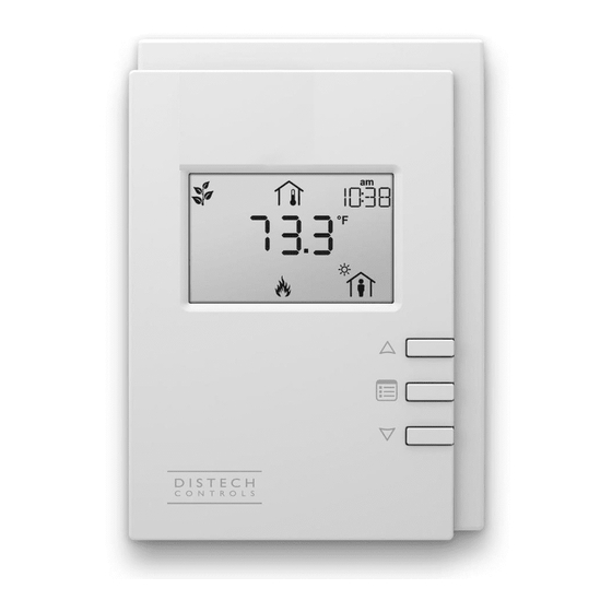
Figure 1-1:
Figure 1-2:
2. Cleaning
Clean the Allure EC-Smart-Vue sensors by polishing with a soft dry
cloth.
3. General Installation Requirements
For proper installation and subsequent operation of the Allure
EC-Smart-Vue sensors, pay special attention to the following
recommendations:
•
It is recommended that the sensor(s) be kept at room temperature
for at least 24 hours before installation to allow any condensation
that may have accumulated due to low temperature during
shipping/storage, to evaporate.
•
Upon unpacking the product, inspect the contents of the carton for
shipping damages. Do not install damaged sensors.
•
The device is designed to operate under environmental conditions
that are specified in its datasheet.
™
Allure
Allure EC-Smart-Vue, Allure EC-Smart-Vue-H/-C/-CH
sensors
Models equipped with a motion sensing window in the
upper left corner: Allure EC-Smart-Vue-M/-CM/-HM/-
CHM sensors
EC-Smart-Vue Series:
1/10
Advertisement
Table of Contents

Subscribe to Our Youtube Channel
Summary of Contents for Distech Allure EC-Smart-Vue Series
-
Page 1: Product Description
• Upon unpacking the product, inspect the contents of the carton for shipping damages. Do not install damaged sensors. • The device is designed to operate under environmental conditions that are specified in its datasheet. www.distech-controls.com 1/10... -
Page 2: Device Dimensions
The Allure EC-Smart-Vue sensors have been specially designed for damage the connector. easy installation. However, certain conditions apply when choosing a Any type of modification to any Distech Controls product will suitable location for the device: void the product’s warranty. -
Page 3: Device Components
7. Device Components 10. Connector and Configuration Jumper Location and Identification Allure EC-Smart-Vues sensors have the following onsite configurable jumpers. Allure EC-Smart-Vue Front Cover, Interior View Pass-Through Subnetwork RJ-45 Connectors PIR LED Enabled Disabled Motion Detection Models Only Subnetwork End of Line Enabled Disabled Local Area Network Type... -
Page 4: Connection Cable
Connect the Allure EC-Smart-Vue sensor to the controller with a All Distech Controls ECB series and ECL series controllers also use standard Cat 5e Ethernet patch cable fitted with RJ-45 connectors. the subnetwork bus to support one or more Allure EC-Smart-Vue sensor(s) using standard structural cabling. -
Page 5: Subnetwork Bus Topology And Eol Terminations
ECL-600 Controller with an ECB-600 / ECL-600 Series Controller Only Figure 14-2: Pins on RJ-45 Jack Face Patch cables fitted with connectors supplied by Distech Controls are wired as T568B. ECx-4XX Sub-Network Bus 2-Wire Shielded 15. Subnetwork Bus Topology and EOL... - Page 6 Screen timeout: 30 sec GEN C Screen timeout: 30 sec MAC A 5. Press the down button once to enter the GEN CFG submenu. 6. Press the Menu button several times until SUBNET ID appears 6. Use the up and down buttons to set the controller’s MAC on the display.
- Page 7 6. Use the Menu button several times until BAUD RATE appears on the display. The current controller’s BAUD rate is shown. LAN Access Connector Screen timeout: 30 sec BACnet MS/TP Adaptor NET+ BAUD with Isolated RS-485 Port NET- Shield Cable Supplied with BACnet MS/TP Adaptor NET+ (White) 7.
- Page 8 Bus Network Topology: 22AWG (0.65mm) Unshielded Twisted Pair Network Cable For One or Two Controller Standard Net to Controllers ONLY: Subnet Port Net to Subnet Port Settings Settings: Optionally Enabled DISABLED - this is the factory default setting Allure EC-Smart-Vue Cat5e communications cable: ·...
-
Page 9: Troubleshooting Guide
Flashing error code 2 with Bell icon Invalid configuration. In EC-gfxProgram, resynchronize the code with the controller. Contact Distech Controls Customer Support. Flashing error code 3 with Bell icon Allure EC-Smart-Vue With EC-gfxProgram, check the configuration of the sensor, for... - Page 10 ©, Distech Controls Inc. 2010. All rights reserved. While all efforts have been made to verify the accuracy of information in this manual, Distech Controls is not responsible for damages or claims arising from the use of this manual. Persons using this manual are assumed to be trained HVAC specialist / installers and are responsible for using the correct wiring procedures and maintaining safe working conditions with fail-safe environments.
Need help?
Do you have a question about the Allure EC-Smart-Vue Series and is the answer not in the manual?
Questions and answers