
Related Manuals for Acson IM-CKA-0501-ACSON


Summary of Contents for Acson IM-CKA-0501-ACSON
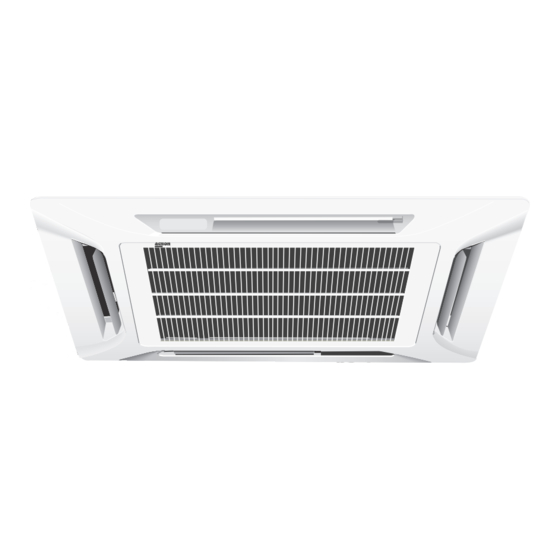
- Page 1 INSTALLATION MANUAL Model: IM-CKA-0501-ACSON CEILING CASSETTE SPLIT TYPE AIR CONDITIONER (A Series) CEILING CASSETTE...
- Page 2 OUTLINE AND DIMENSIONS Indoor Unit (CKA Series) • (With Wireless Remote Control & With Wired Remote Control) All dimensions are in mm / (in) MODEL CK / 5CK 20A/AR CK / 5CK 25A/AR CK / 5CK 30A/AR (32,2) (32,2) (14,3) (13,2) (1,1) (36,6)
- Page 3 Outdoor Unit (SL - B Series) All dimensions are in mm / (in) 840 (33,1) 124 (4,9) 592 (23,3) 124 (4,9) 5 (0,2) 330 (13,0) 840 (33,1) 160 (6,3) 330 (13,0) 5 (0,2) 297 (11,7) (3,3) (4,2) Dimension 20B / 20BR 78,5 25B / 25BR (33,1) (25,4) (13,0) (11,7) (12,2) (24,6) (1,6)
- Page 4 Outdoor Unit : SL20C / 25C / 28C & CR All dimensions are in mm / (in) FOR SL25C/CR ONLY Dimension 20C/CR (33,7) (24,7) (12,9) (20,0) (7,1) (1,7) (3,7) (5,9) (4,0) (4,4) (23,7) (5,0) (6,4) (0,7) (1,9) 25C/CR 28C/CR (33,7) (28,7) (12,9) (20,2) (7,2) (1,7) (3,7)
- Page 5 Sharp edges and coil surfaces are potential locations which may cause ! Caution injury hazards. Avoid from being in contact with these places. Les bords coupants et les surfaces du refroidisseur tuulaire présentent ! Avertissement un risque de blessure. Mieux vaut éviter le contact avec ces endroits. Scharfe Kanten und Wärmetauscherflächen stellen eine Gefahrenquelle dar.
-
Page 6: Installation Manual
5LC35C / A5LC35C 5SL40CR / A5LC40CR 5SL40C / A5LC40C CK50AR / ACK50AR CK50A /ACK50A SL50CR / ALC50CR SL50C / ALC50C 4SL50CR / A4LC50CR 4SL50C / A4LC50C 5CK50AR / A5CK50AR 5CK50A / A5CK50A 5SL50CR / A5SL50CR 5SL50C / A5LC50C IM-CKA-0501(2)-Acson Part No.:A08019025475... -
Page 7: Table Of Contents
CONTENTS - Special Precautions When Charging Unit With - Outline And Dimensions page i – iv Copeland Scroll Compressors page 12 - Safety Precautions page - Accessory Parts page 13 - Installation Diagram page - Indicator Lights page 13 - Installation Of The Indoor Unit page - Overall Checking page 14... -
Page 8: Installation Diagram
INSTALLATION DIAGRAM Wireless Remote Control Drain Hose Indoor unit Air Discharge Louver IR Receiver LED Light Front Panel Air Intake Grille Air Filter (behind the grille) Air Discharge Louver Remote Control Refrigerant Piping Air Intake Air Intake Outdoor unit Air Discharge Wired Remote Control Drain Hose Indoor unit... -
Page 9: Installation Of The Indoor Unit
INSTALLATION OF THE INDOOR UNIT Preliminary Site Survey • Electrical supply and installation is to conform to local authority's (e.g. National Electrical Board) codes and regulations. • Voltage supply fluctuation must not exceed + 10% of rated voltage. Electricity supply lines must be independent of welding transformers which can cause high supply fluctuation. - Page 10 Drain Piping Work • Drain pipe must be in downward gradient for smooth drainage. • Avoid installing the drain pipe in up and down slope to prevent reversed water flow. • During the drain pipe connection, be careful not to exert Indoor Unit extra force on the drain connector at indoor unit.
-
Page 11: Installation Of The Outdoor Unit
NOTE Install the front frame panel firmly to prevent cool air leakage which will cause condensation and water dripping. Indoor Unit Cool Cool Air Leak Air Leak Ceiling Board Ceiling Board Panel Panel Bad Installation Good Installation Air intake grille installation Frame •... -
Page 12: Refrigerant Piping Work
REFRIGERANT PIPING WORK Refrigerant piping is important in particular. Refrigeration cycle of the split air conditioner is realized by the perfect piping work. Piping length and elevation If the piping is too long, both the capacity and reliability of unit will drop. As the number of bends increase, resistance to flow of refrigerant system increases, thus lowering cooling capacity and as a result the compressor may become defective. -
Page 13: Electrical Wiring Connection
Additional Charge (In gram) The refrigerant is pre-charge in the outdoor unit, but additional charge of refrigerant after vacuuming is necessary. Follow the recommendation as tabulated below. Cooling Only (R22) Heatpump (R22) 10m 15m 20m 25m 30m 35m 10m 15m 20m 25m 30m 35m CK20A CK20AR CK25A... - Page 14 CK40A & CK50A Indoor 5CK30/40A CK40A CK50A Model Outdoor 5SL35C SL40C SL50C Voltage range** 380-420V/3Ph /50Hz+ N+ or 208-230V/3Ph/60Hz+N+ Recommended fuse* (A) 10/20 16/25 Power supply cable size* (mm ) (50/60Hz) 1.5/2.5 2.5/4.0 Number of conductors Interconnection cable size* (mm ) (50/60Hz) 1.5/1.5 1.5/1.5...
- Page 15 Outdoor Coil Sensor CK30AR <> SL28CR Interconnection Cable Outdoor Unit Indoor Unit COMP Terminal Terminal COMP Block Block Power Supply Cable There must be a double pole switch with minimum 3mm contact gap and fuse/circuit breaker as recommended in the fixed installation circuit.
-
Page 16: Special Precautions When Dealing With R410A Unit Page
SPECIAL PRECAUTIONS WHEN DEALING WITH R410A UNIT R410A is a new HFC refrigerant which does not damage the • Use tools and materials exclusively for refrigerant R410A. ozone layer. The working pressure of this new refrigerant is Tools exclusively for R410A are manifold valve, charging 1.6 times higher than conventional refrigerant (R22), thus hose, pressure gauge, gas leak detector, flare tools, torque proper installation / servicing is essential. -
Page 17: Special Precautions When Charging Unit With Copeland Scroll Compressors
SPECIAL PRECAUTIONS WHEN CHARGING UNIT WITH COPELAND SCROLL COMPRESSORS These precautions are intended for use with Copeland Scroll compressors only with R22, R407C, R134A, R404A, R507 and R410A refrigerants but are not applied to Copeland reciprocating compressors or competitive Scroll compressors. Scroll compressors have a very high volumetric efficiency and quickly pump a deep vacuum if there is insufficient refrigerant in the system or if refrigerant is added too slowly. -
Page 18: Accessory Parts
ACCESSORY PARTS Short Duct Specification • The indoor unit is provided with air discharge and air intake “knock-out” hole for duct connection. However the connec- tion of the short duct for air discharge is possible on only one side. • The use of short duct for air discharge will improve airflow distribution if there is an obstruction (such as a lighting fixture) or in a long, narrow room or an L-shaped room. -
Page 19: Overall Checking
Faulty Indication Action POWER TIMER SLEEP/HEAT Other LEDs Blink 1 time Blink Fan Room Sensor Open or Short Blink 2 times Blink Dry & Fan Indoor Coil Sensor Open Blink 3 times Blink Dry Outdoor Coil Sensor Open Compressor Overload / Blink 1 time Blink Cool Indoor Coil Sensor Short /... -
Page 20: Standard Operation Conditions
STANDARD OPERATION CONDITIONS Heat Pump Unit Cooling unit Temperature Ts °C / °F Th °C / °F Temperature Ts °C / °F Th °C / °F Minimum indoor Minimum indoor 10 / 50 – 19.4 / 66.9 13.9 / 57.0 temperature temperature Maximum indoor... -
Page 21: Troubleshooting
TROUBLESHOOTING If any malfunction of the air conditioner unit is noted, immediately switch off the power supply to the unit. Check the following fault conditions and causes for some simple troubleshooting tips. Fault Causes / Action 1. The compressor does not start operate after 3 minutes - Protection against frequent starting. - Page 22 • In the event that there is any conflict in the interpretation of this manual and any translation of the same in any language, the English version of this manual shall prevail. • The manufacturer reserves the right to revise any of the specification and design contain herein at any time without prior notification.
Need help?
Do you have a question about the IM-CKA-0501-ACSON and is the answer not in the manual?
Questions and answers