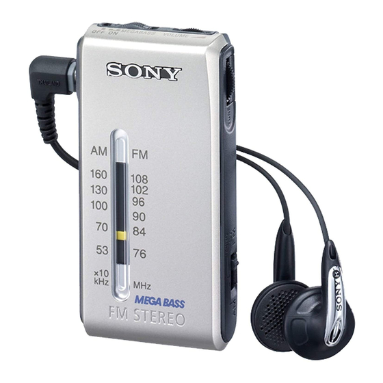
Sony Walkman SRF-S84 Service Manual
Fm stereo/am radio
Hide thumbs
Also See for Walkman SRF-S84:
- User manual ,
- Operating instructions (2 pages) ,
- Operating instructions (2 pages)
Table of Contents
Advertisement
Quick Links
SERVICE MANUAL
Ver 1.0 2002.02
SPECIFICATIONS
Frequency range
FM: 87.5-108 MHz
AM: 530 -1605kHz
Output
2 (stereo earphones) jack (Ø3.5mm stereo minijack) load impedance 16Ω
Power output
3.6mW + 3.6mW (at 10% harmonic distortion)
Power requirements
1.5 V DC, one R03 (rize AAA)
Dimensions
Approx.39.5 × 78.5 × 16.5 mm (w / h / d)(Approx. 1
not incl. projecting parts and contorols
Mass Approx.
61.2g (2.16 oz) incl. abattery and stereo earphones
Accessories supplied
stereo earphones (1)
Design and specifications are subject to change without notice
SRF-S84
Australian Model
Chinese Model
× 3
×
9
1
21
/
/
/
inches)
16
8
32
FM STEREO/AM RADIO
E Model
Advertisement
Table of Contents

Related Manuals for Sony Walkman SRF-S84


Summary of Contents for Sony Walkman SRF-S84
- Page 1 SRF-S84 SERVICE MANUAL E Model Australian Model Ver 1.0 2002.02 Chinese Model SPECIFICATIONS Frequency range FM: 87.5-108 MHz AM: 530 -1605kHz Output 2 (stereo earphones) jack (Ø3.5mm stereo minijack) load impedance 16Ω Power output 3.6mW + 3.6mW (at 10% harmonic distortion) Power requirements 1.5 V DC, one R03 (rize AAA)
-
Page 2: Table Of Contents
SRF-S84 TABLE OF CONTENTS Specifications ................1 Flexible Circuit Board Repairing • Keep the temperature of the soldering iron around 270°C during 1. GENERAL repairing. Location and Function of Controls ........2 • Do not touch the soldering iron on the same conductor of the circuit board (within 3 times). -
Page 3: Disassembly
SRF-S84 SECTION 2 DISASSEMBLY The equipment can be removed using the following procedure. Cabinet (rear) Main board Note : Follow the disassembly procedure in the numerical order given. 2-1. CABINET (REAR) 3 Claws Cabinet (front) 2 Claw Cabinet (rear) 4 Screw(B1.7 x 8) 1 Screw(B1.7 x 8) -
Page 4: Dial Pointer Installation
SRF-S84 SECTION 3 DIAL POINTER INSTALLATION Note : Follow the installation procedure in the numerical order given. 1 Insert the pointer into the cabinet (rear). 2 Slide the pointer to arrow direction. Pointer Cabinet (rear) 3 Install the gear (tuning capacitor), and engage with pointer as Gear (tuning cpacitor) a figure. -
Page 5: Adjustments
SRF-S84 SECTION 4 ADJUSTMENTS • Repeat the procedures in each adjustment several times, and the Connect Location : TUNER SECTION 2nd OSC Adjustment 0dB = 1µV [MAIN BOARD] (SIDE B) frequency coverage and tracking adjustments should be finally Procedure : done by the trimmer capacitors. -
Page 6: Diagrams
SRF-S84 SECTION 5 DIAGRAMS 5-1. BLOCK DIAGRAMS FM/AM FRONT-END,IF AMP,MPX MEGA BASS AMP HEADPHONE AMP FM LPF L-CH IN 2 VCO, IN 1 OUT 1 OUT 2 FM RF IN LIMITER FM RF AM RF R-CH DISCRI FM RF L1,CT2... - Page 7 SRF-S84 5-2. PRINTED WIRING BOARDS MAIN BOARD (SIDE A) MAIN BOARD (SIDE B) DRY BATTERY SIZE "AAA" (IEC DESIGNATION R03) 1PC, 1.5V -2 -1 -2 -1 Semiconductor Location TP10 Ref. No. Location 1-682-982- Note: FERRITE-ROD • X : parts extracted from the component side.
- Page 8 SRF-S84 5-3. SCHEMATIC DIAGRAM Note: • All capacitors are in µF unless otherwise noted. pF: µµF 50 WV or less are not indicated except for electrolytics and tantalums. • All resistors are in Ω and W or less unless otherwisespecifed.
- Page 9 SRF-S84 IC BLOCK DIAGRAMS IC1 CXA1129N-T4 30 29 24 23 FM/TV 38KHz FM/AM R CH OVER LOAD LOCAL FM/TV L CH LEVEL SELECT CONTROL FM/TV FM/TV RF AMP π/2 COUNTER DISCRI BUFF LOAD CONTROL SELECT FM/TV LIMITTER 38KHz MUTE AM IF AMP...
-
Page 10: Exploded View
3-236-171-01 CABINET (FRONT) A-3021-741-A MAIN BOARD, COMPLETE 3-236-176-01 KNOB (POWER) 3-236-181-01 TERMINAL (-), BATTERY 3-236-178-01 PLATE, TRANSPARENT 3-238-306-01 WASHER 3-236-179-01 EMBLEM (NO.3), SONY 3-919-915-02 KNOB (TUNING) 3-236-174-21 PANEL, FRONT...(BLUE) 3-919-918-01 GEAR (MIDWAY) 3-236-174-41 PANEL, FRONT...(GOLD) 3-919-919-01 GEAR (TUNING CAPACITOR) 3-236-172-11 CABINET (REAR) (AUS,CH,TW) -
Page 11: Electrical Parts List
SRF-S84 SECTION 7 MAIN ELECTRICAL PARTS LIST NOTE : • Due to standardization, replacements in the • SEMICONDUCTORS When indicating parts by reference num- In each case, u : µ , for example : parts list may be different from the parts ber, please include the board. - Page 12 SRF-S84 MAIN Ref. No. Part No. Description Remark <RESISTOR> 1-216-813-11 METAL CHIP 1/16W 1-216-821-11 METAL CHIP 1/16W 1-216-795-11 RES-CHIP 1/10W 1-216-843-11 METAL CHIP 1/16W 1-216-847-11 METAL CHIP 150K 1/16W 1-216-847-11 METAL CHIP 150K 1/16W 1-216-829-11 METAL CHIP 4.7K 1/16W 1-216-845-11 METAL CHIP...
- Page 13 SRF-S84...
- Page 14 SRF-S84 REVISION HISTORY Clicking the version allows you to jump to the revised page. Also, clicking the version at the upper right on the revised page allows you to jump to the next revised page. Ver. Date Description of Revision...
Need help?
Do you have a question about the Walkman SRF-S84 and is the answer not in the manual?
Questions and answers