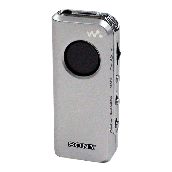
Sony SRF-M97 Service Manual
Fm stereo/am pll synthesized radio
Hide thumbs
Also See for SRF-M97:
- User manual ,
- Specifications (2 pages) ,
- Operating instructions (2 pages)
Table of Contents
Advertisement
Quick Links
SERVICE MANUAL
Ver. 1.1 2004.12
Time display:
North and South American
12-hour system
countries/regions
Other countries/regions
24-hour system
Frequency range:
Model for North and South America
countries/regions
Band
Frequency range
Channel step
FM
87.5 - 108 MHz
0.1 MHz
AM
530 - 1 710 kHz
10 kHz
531 - 1 710 kHz
9 kHz
Model for Other countries/regions
Band
Frequency range
Channel step
FM
87.5 - 108 MHz
0.05 MHz
AM
531 - 1 602 kHz
9 kHz
530 - 1 610 kHz
10 kHz
Tourist model
Band
Frequency range
Channel step
FM
76 - 108 MHz
0.05 MHz
AM
531 - 1 710 kHz
9 kHz
530 - 1 710 kHz
10 kHz
Sony Corporation
9-879-289-02
Personal Audio Company
2004L05-1
Published by Sony Engineering Corporation
© 2004.12
SPECIFICATIONS
Output:
i (headphones) jack
(ø3.5 mm, stereo minijack)
Power output:
2 mW + 2 mW (at 10 % harmonic distortion)
Power requirements:
1.5 V DC, one R03 (size AAA) battery
Auto Power off function:
Approx. 30 minutes, 60 minutes, 90minutes, 120
minutes, and off
Dimensions:
Approx. 37.4 × 84.6 × 21.6 mm (w/h/d)
× 3
×
1
3
7
(Approx. 1
/
/
/
inches)
2
8
8
incl. projecting parts and controls
Mass:
Approx. 58.5 g (2.06 oz.)
incl. battery and the headphones
Accessories supplied
Stereo headphones (1)
Sony
R03 (size AAA) battery (1) (for trial*) (Tourist model)
* The supplied battery is for trial. We recommend you to
purchase a Sony alkaline LR03 (size AAA) battery.
Design and specifications are subject to change
without notice.
FM STEREO/AM PLL SYNTHESIZED RADIO
SRF-M97
Australian Model
Chinese Model
Tourist Model
Battery Life (Approx. hours)
When using
Sony alkaline LR03
(size AAA)
Sony R03
(size AAA)
* Measured by JEITA (Japan Electronics and
Information Technology Industries Association)
standards. The actual battery life may vary
depending on the circumstance of the unit.
US Model
AEP Model
E Model
(JEITA*)
FM
AM
40
65
16
30
Advertisement
Table of Contents

Related Manuals for Sony SRF-M97


Summary of Contents for Sony SRF-M97
- Page 1 530 - 1 610 kHz 10 kHz * The supplied battery is for trial. We recommend you to Tourist model purchase a Sony alkaline LR03 (size AAA) battery. Band Frequency range Channel step Design and specifications are subject to change without notice.
-
Page 2: Table Of Contents
SRF-M97 Notes on chip component replacement TABLE OF CONTENTS • Never reuse a disconnected chip component. • Notice that the minus side of a tantalum capacitor may be GENERAL ..............3 damaged by heat. DISASSEMBLY Flexible Circuit Board Repairing 2-1. Disassembly Flow ............4 •... -
Page 3: General
SRF-M97 SECTION 1 This section is extracted from instruction manual. GENERAL Front Setting the Clock Parte frontal The clock system varies depending on the model you own. 12-hour system: “AM 12:00” = midnight Display Window 24-hour system: “0:00” = midnight Ventana del visualizador The time display of this clock is a 24-hour system. -
Page 4: Disassembly
SRF-M97 SECTION 2 DISASSEMBLY • This set can be disassembled in the order shown below. 2-1. DISASSEMBLY FLOW 2-2. MAIN BOARD, CABINET (FRONT) ASSY (Page 4) 2-3. SIDE PANEL SECTION, CABINET (REAR) ASSY (Page 5) 2-4. AMP BOARD (Page 5) Note: Follow the disassembly procedure in the numerical order given. -
Page 5: Side Panel Section, Cabinet (Rear) Assy
SRF-M97 2-3. SIDE PANEL SECTION, CABINET (REAR) ASSY 4 cabinet (rear) assy 2 claw 3 side panel section knob (rear) 1 two screws (1.4) Note : On installation of side panel section and cabinet (rear) assy, adjust the position of switch S203 (S203) and knob (rear). -
Page 6: Electrical Adjustments
SRF-M97 Ver. 1.1 SECTION 3 ELECTRICAL ADJUSTMENTS ( ): US model 0 dB=1 µV [ ]: Tourist model [AM] AM VT VOLTAGE ADJUSTMENT Setting: Reading on Adjustment Part Frequency Display Band: AM Digital Voltmeter 1.2 ± 0.05 V 531 (530) [531] kHz Put the lead-wire 7.5 (7.9) [7.9] ±... - Page 7 SRF-M97 Adjustment Location: – MAIN BOARD (Component Side) – AM VT Voltage Adjustment FM Tracking Adjustment AM Tracking Adjustment – MAIN BOARD (Conductor Side) – (VT) (ANT) (RF GND)
-
Page 8: Diagrams
SRF-M97 SECTION 4 DIAGRAMS • Note for Printed Wiring Boards and Schematic Diagrams Note on Printed Wiring Board: Note on Schematic Diagram: • X : parts extracted from the component side. • All capacitors are in µF unless otherwise noted. (p: pF) •... -
Page 9: Schematic Diagram
SRF-M97 Ver. 1.1 • See page 12 for Waveforms. • See page 12 for IC Block Diagrams. • See page 13 for IC Pin Function Description. 4-1. SCHEMATIC DIAGRAM ∗ C12 (JE) (VT) (EXCEPT JE) 100k 220k Q5,6 ∗ ∗... -
Page 10: Printed Wiring Board - Main Board
SRF-M97 Ver. 1.1 4-2. PRINTED WIRING BOARD – MAIN Board – :Uses unleaded solder. • Semiconductor Location Ref. No. Location MAIN BOARD MAIN BOARD (CONDUCTOR SIDE) (COMPONENT SIDE) T101 D101 DC/DC S101 C128 R134 CONVERTER C127 POWER Q104 D102 R131... -
Page 11: Printed Wiring Board - Amp Board
SRF-M97 Ver. 1.1 4-3. PRINTED WIRING BOARD – AMP Board – :Uses unleaded solder. J201 AMP BOARD AMP BOARD (COMPONENT SIDE) (CONDUCTOR SIDE) R302 L201 RV201 C217 R209 L203 C222 R211 C216 L202 C221 R210 Q201 C218 R207 S201 ENT/BAND... - Page 12 SRF-M97 • Waveforms • IC Block Diagrams – MAIN Board – – MAIN Board – IC1 TA2154AFN-EL IC101 tg (XOUT) 0.4 Vp-p BUFFER FM/AM/TV 13.3 µ s PW SW 200 mV/DIV, 5 µ s/DIV 1/8 OR 1/16 LEVEL BUFFER Q103 (Collector),...
- Page 13 SRF-M97 Ver. 1.1 • IC Pin Function Description MAIN BOARD IC101 TC9329AFAG-609 (S.D) (SYSTEM CONTROLLER) Pin No. Pin Name Description 1 to 4 COM1 to COM4 Common drive signal output to the liquid crystal display 5 to 16 S1 to S12...
-
Page 14: Exploded Views
SRF-M97 Ver. 1.1 SECTION 5 EXPLODED VIEWS NOTE: • Items marked “*” are not stocked since they • -XX and -X mean standardized parts, so they may have some difference from the original are seldom required for routine service. Some one. -
Page 15: Cabinet (Rear) Section
SRF-M97 Ver. 1.1 5-2. CABINET (REAR) SECTION Ref. No. Part No. Description Remark Ref. No. Part No. Description Remark 3-252-824-01 SCREW (1.4) 3-244-857-01 CLIP 2-189-418-01 HOLDER (JACK) 7-626-305-31 SPRING-PIN 1X8 2-189-428-01 TERMINAL (–), BATTERY 2-189-427-01 KNOB (REAR) A-1079-165-A AMP BOARD, COMPLETE (JE) -
Page 16: Electrical Parts List
SRF-M97 Ver. 1.1 SECTION 6 ELECTRICAL PARTS LIST NOTE: • Items marked “*” are not stocked since they • Due to standardization, replacements in the When indicating parts by reference parts list may be different from the parts are seldom required for routine service. - Page 17 SRF-M97 Ver. 1.1 MAIN Ref. No. Part No. Description Remark Ref. No. Part No. Description Remark R202 1-218-965-11 RES-CHIP 1/16W (JE) 1-162-908-11 CERAMIC CHIP 0.25PF 50V R202 1-218-969-11 RES-CHIP 1/16W (EXCEPT JE) (EXCEPT AEP, JE) 1-162-964-11 CERAMIC CHIP 0.001uF 1-162-964-11 CERAMIC CHIP 0.001uF...
- Page 18 SRF-M97 Ver. 1.1 MAIN Ref. No. Part No. Description Remark Ref. No. Part No. Description Remark 1-414-684-11 INDUCTOR 27nH (EXCEPT JE) C111 1-162-964-11 CERAMIC CHIP 0.001uF 1-414-685-11 INDUCTOR 33nH (JE) C112 1-162-923-11 CERAMIC CHIP 47PF 1-419-843-21 COIL, FERRITE-ROD ANTENNA (MW)
- Page 19 SRF-M97 Ver. 1.1 MAIN Ref. No. Part No. Description Remark Ref. No. Part No. Description Remark R109 1-218-953-11 RES-CHIP 1/16W R110 1-218-953-11 RES-CHIP 1/16W R111 1-218-953-11 RES-CHIP 1/16W R112 1-218-953-11 RES-CHIP 1/16W R113 1-218-953-11 RES-CHIP 1/16W R114 1-218-961-11 RES-CHIP 4.7K...
- Page 20 SRF-M97 REVISION HISTORY Clicking the version allows you to jump to the revised page. Also, clicking the version at the upper right on the revised page allows you to jump to the next revised page. Ver. Date Description of Revision 2004.11...
Need help?
Do you have a question about the SRF-M97 and is the answer not in the manual?
Questions and answers