Telex Audiocom WM1000 User Instructions
Audiocom wm1000/2000 wall mount intercom station
Hide thumbs
Also See for Audiocom WM1000:
- User instructions (10 pages) ,
- Addendum (1 page) ,
- User instructions (24 pages)

Related Manuals for Telex Audiocom WM1000


Summary of Contents for Telex Audiocom WM1000
- Page 1 Model WM1000/WM2000 Wall Mount Intercom Stations User Instructions 9350-7621-000 Rev G 04/2009...
-
Page 2: Proprietary Notice
All shipments of product should be made via disclosed herein were originative by and are UPS Ground, prepaid (you may request from the property of Bosch Security Systems, Inc. Factory Service a different shipment Bosch reserves all patent, proprietary design, method). -
Page 3: Table Of Contents
Table Contents WM1000/WM2000 ................1 Introduction ...................1 Description ....................1 Reference View ..................2 Features ....................3 Installation ....................6 Configuration Switch Pre-check ............6 Mic Kill DIP Switch (DIP Switch 1) ............6 DC Call Enable (DIP Switch 2) ............6 Incoming Call Beep (DIP Switch 3) .............6 Headset Microphone Type Selection (DIP Switch 4) ......7... -
Page 5: Wm1000/Wm2000
The WM1000 is a single-channel station. The WM2000 provides switch-selectable access to either of two (2) intercom channels. The WM1000 and WM2000 are ideal when users need access to the intercom station from strategic locations where a desktop station would not be suitable or they do not wish to carry around a belt-pack station. -
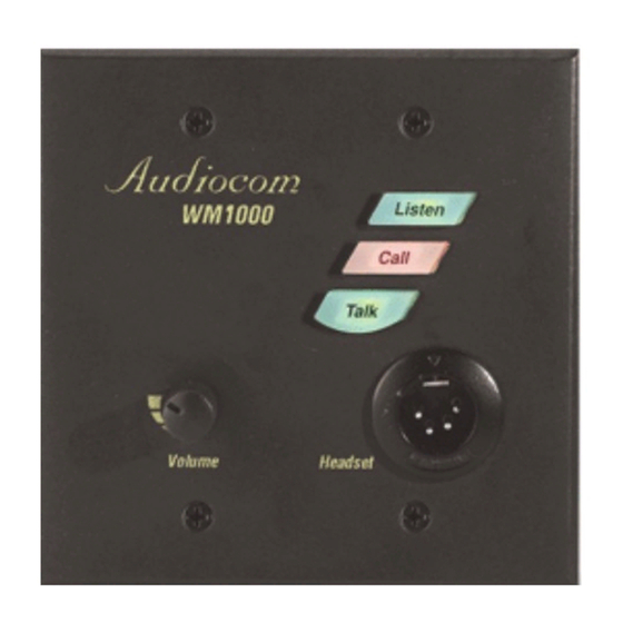
Page 6: Reference View
Reference View Reference View, WM-2000 shown. FIGURE 1. -
Page 7: Features
Features NOTE: The numbered features list in Channel Select Switch (WM-2000 Only) - The channel select switch is used to switch between intercom channels one and two. The switch lights green for channel one and red for channel two. Intercom Listen Key - The intercom listen key can be used in both momentary (push-to-listen) and latching (hands-free listen) modes. - Page 8 Intercom Talk Key: The talk key can be used in both momentary PTT (push-to-talk) and latching (hands-free talk) mode. Momentary Mode - Press and hold the TALK button, then speak into the microphone. The green talk LED remains lit while the TALK button is held.
- Page 9 Call Beep - An optional call beep tone can be used for incoming call notification. Headset Mic Selection - Balanced or unbalanced microphone may be selected. DC Call Enable: - This may be turned on to use the intercom station with intercom systems that use DC call signaling.
-
Page 10: Installation
DC Call Enable (DIP Switch 2) Leave this switch in the open position for Audiocom applications. Set it to the closed position if the WM1000/2000 will be used in a Clear-Com intercom system. Incoming Call Beep (DIP Switch 3) By default, incoming calls are indicated by a red-flashing Call key and a beep tone in the headphones. -
Page 11: Headset Microphone Type Selection (Dip Switch 4)
Configuration Switch Settings TABLE 1. SETTINGS SWITCH DEFAULT DESCRIPTION NUMBER SETTINGS OPEN=OFF, CLOSED =ON Closed: Disabled, No Mic Kill Mic Kill Receive Open Open: Enabled, Mic Kill Active Closed: DC (SW1 set to UNBAL) Call Signal Method Open Open: Audiocom (SW1 set to BAL) Closed: Disabled Incoming Call Beep Open... -
Page 12: Intercom Channel Connections
The WM1000/2000 mounts in a standard two-gang electrical box. Some example intercom system configurations are shown in Figure 2 through Figure 5. Detailed connections for the WM1000/2000 are shown in Figures 6 and 7. There are two (2) basic methods for connecting the WM1000/2000: •... -
Page 13: All Locally Powered Intercom Stations (Dry Lines)
issue, the operating range is now limited only by the audio transmission range, which is several miles. Another advantage to this method is more stations can be connected to the intercom channels. When local power is supplied to an intercom station, the station detects this and automatically disconnects from the phantom power supply. -
Page 14: Power Up
OFF, then ON. Sidetone Adjustment The WM1000/2000 uses full-duplex audio (the same as conventional telephone lines) in which the talk and listen audio are sent and received on the same wires. When you talk on a channel, you also hear your own voice back in the headphones. If you are using open-ear style headphones, this could cause unwanted feedback, since the microphone may pick up your returned voice audio and re-amplify it. - Page 15 In isolate mode, each intercom channel is a separate party line, and total current for each channel is limited to 1 amp. Note, both WM1000 and WM2000 stations may be connected, depending on each locations need to communicate with one or two channels.
- Page 16 FIGURE 3. Intercom Stations. Figure 3 shows a single-channel intercom system using one PS2001L with WM1000 Intercom Stations. The PS2001L may be set to either combine or isolate mode. In combine mode, all intercom stations talk on a single party line, and total current for the channel is 2 amps.
- Page 17 Each intercom channel is a separate party line, and total current for each channel is limited to 2 amps. Note, both WM1000 and WM2000 Intercom Stations may be connected, depending on each locations need to communicate with one or two intercom channels.
- Page 18 An example of an intercom system using all local powered stations, with no power being distributed on the intercom channels (dry lines). WM2000 stations are shown, but WM1000 stations by also be used. Since an Audiocom power is not used, the install must connect a line termination somewhere in each channel for proper...
- Page 19 Audiocom mode connections for WM1000 Intercom Station. FIGURE 6.
- Page 20 Audiocom mode connections for a WM2000 Intercom Station FIGURE 7. Audiocom mode line termination for dry line operation (one required for FIGURE 8. each channel).
-
Page 21: Operation
Operation Channel Select (WM2000 Only) To change the WM2000 channel, do the following: > Tap the Ch Select key to select channel 1 or 2. The key is green when channel 1 is selected and red when channel two is selected. -
Page 22: Unbalanced Mode
Unbalanced Mode To use the WM1000/2000 in a Clear-Com Intercom System, do the following Set SW1 to the UNBAL position. Set DIP switch 2 to the Closed position. Connect the Clear-Com channel wires using the Unbalanced Mode Intercom Channel pin-out information listed in the “Specifications” on... -
Page 23: Specifications
Pin 4 Intercom channel 1 audio high +24VDC Specifications phantom power Pin 5 Intercom channel 2 audio low +24VDC General phantom power Power Requirements Pin 6 Intercom channel 2 audio high +24VDC phantom power Phantom Power: 24VDC nominal (30VDC), 150mA Intercom Channel, Unbalanced Mode (SW-1 set to UNBAL position) Local Power: 15VDC, 150mA...