
Related Manuals for Telex Audiocom EMS-4001


Summary of Contents for Telex Audiocom EMS-4001
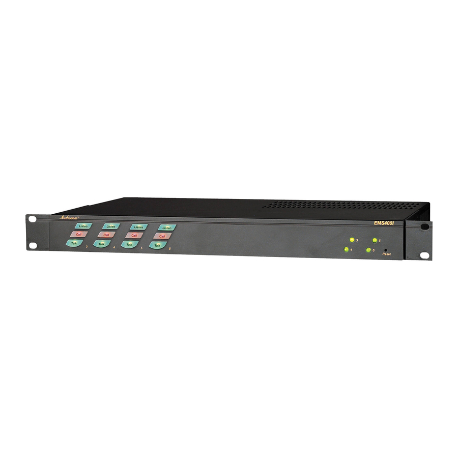
- Page 1 Model EMS-4001 Expansion Master Station User Instructions 9350-7713-000 Rev C 04/2006...
- Page 2 OTICE The product information and design disclosed herein were originated by and are the property of Telex Communications, Inc. Telex reserves all patent, proprietary design, manufacturing, reproduction, use and sales rights thereto, and to any article disclosed therein, except to the extent rights are expressly granted to others.
-
Page 3: Table Of Contents
Chapter 1 Introduction ... 3 Description ... 3 Features ... 4 Chapter 2 Installation ... 7 Unpacking... 7 Configuration Pre-check ... 7 DIP Switches ... 8 Program Interrupt DIP Switches ... 8 Audio Call Send and Receive DIP Switches ... 8 Balanced / Unbalanced Switch ... -
Page 5: Introduction
The EMS-4001 adds four powered intercom channels to an MS-2001 Master Station, and it provides talk, listen and call buttons for the added channels. Up to four EMS-4001 Expansion Master Stations may be connected to the MS-2001 to add up to 16 channels (18 channels total). -
Page 6: Features
EXP IN and EXP OUT connectors. An EXP IN/OUT cable is supplied with each EMS-4001. Speakers: Usually, the listen mix of all four EMS-4001 channels is sent to the MS-2001 speaker or headset via the EXP IN connector. - Page 7 Features Configuration switches, Jumpers and Sidetone Controls: These let you customize the operation of the EMS-4001 to match your intercom system requirements. EMS-4001 Internal DIP switches, jumpers, and adjustments FIGURE 2.
- Page 8 Introduction...
-
Page 9: Installation
The EMS-4001 is supplied with the following items. Contact the shipper or your Audiocom dealer immediately if anything is damaged or missing. Detach and fill out the registration card and return it to Telex to properly register your intercom station. -
Page 10: Dip Switches
Each intercom channel has a dedicated program input. These can be used to feed background music, mix-minus audio (for broadcasting usage) etc. to the channels. If external program sources will be connected to the EMS-4001, you have a choice of whether or not you want the program audio to interrupt (shut off) on the intercom channel while the MS-2001/EM-4001 station operator is talking. - Page 11 Sidetone Trimmers EMS-4001 configuration switch settings TABLE 1. SWITCH NUMBER DESCRIPTION SW1-1 Program Interrupt, CH6 SW1-2 Program Interrupt, CH5 SW1-3 Program Interrupt, CH4 SW1-4 Program Interrupt, CH3 SW1-5 Audio Call Send, CH3 SW1-6 Audio Call Receive, CH3 SW1-7 Audio Call Send, CH4...
-
Page 12: Mounting Configurations
Program 6 direct to Headset or Speaker Mounting Configurations The EMS-4001 mounts in a standard 19-inch equipment rack and is 1 rack unit high. Install the two supplied rack mount cosmetic covers when installing the EMS-4001 in the rack. When rack mounting components, you may not be able to access the sidetone trimmers after the components have been mounted. - Page 13 Cables Shielded audio cable. Must have male 3-pin XLR connector at one end for connection to the XP-USPG or XP-4PA output. Pin-out for PA output is as follows: Pin 1: common Pin 2: + PA output Pin 3: - PA output...
- Page 14 Installation...
-
Page 15: Operation
Power-Up Plug in the power cord. The EMS-4001 channels power-up identically to channels one and two of the MS-2001. Refer to the MS-2001 User Instructions for all power-up information. The MS-2001 and EMS-4001 can be powered up in any order. -
Page 16: Operation
Operation FIGURE 4. Operation The EMS-4001 channels operate identically to channels one and two of the MS-2001. Refer to the MS-2001 User Instructions for all operating information. Specifications GENERAL Input and Output Power: AC Input: 100-200 VAC, 50/60 Hz Channel Power (each channel): 24 ±1 VDC, 2A Dimensions: 1.75”... - Page 17 Specifications...
Need help?
Do you have a question about the Audiocom EMS-4001 and is the answer not in the manual?
Questions and answers