Table of Contents
Advertisement
Quick Links
QQ
3 7 63 1515 0
SERVICE MANUAL
Ver 1.0 2002.02
• Manufactured under license from Dolby Laboratories and Digital
Theater Systems,Inc.
"Dolby ","AC-3 ","Pro Logic ",the "AAC " logo and the double-D
symbol ; are trademarks of Dolby Laboratories.
"DTS " and "DTS VIRTUAL " are trademarks of Digital Theater
TE
L 13942296513
Systems, Inc.
• DP-IF8000 is the component model block one in
MDR-DS8000.
COMPONENT MODEL NAME FOR MDR-DS8000
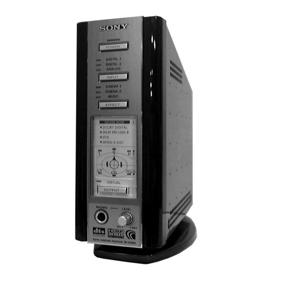
DIGITAL SURROUND PROCESSOR
CORDLESS STEREO HEADPHONES
www
.
Sony Corporation
9-873-528-01
2002B0200-1
Parsonal Audio Company
© 2002. 02
Published by Sony Engineering Corporation
http://www.xiaoyu163.com
DP-IF8000
MDR-IF8000
x
ao
u163
y
i
http://www.xiaoyu163.com
DP-IF8000
2 9
8
Decoder functions
Q Q
3
6 7
1 3
1 5
Virtual sound function
Modulation System
Secondary carrier wave frequency
Transmission distance
Transmission range
Distortion rate
Audio inputs
Power requirements
Dimensions (w/h/d)
Mass
Design and specifications are subject to change without notice.
DIGITAL SURROUND PROCESSOR
co
.
9 4
2 8
US Model
Canadian Model
AEP Model
SPECIFICATIONS
Dolby Digital
Dolby Pro Logic II
DTS
DTS-ES 6.1ch
MPEG-2 AAC
0 5
8
2 9
9 4
2 8
OFF
Virtual front
Virtual surround 5.1 & 6.1
DQPSK
4.5 MHz
Approx. 10 m to the front
12 – 24,000 Hz
1% or less (1 kHz)
Optical input
(rectangular-type) × 2
Analogue input
(pin jack left/right) × 1
DC 9 V (from the supplied AC
power adaptor)
Approx. 85 × 190 × 200mm (3
/
× 7
/
1
1
7
inch)
2
8
Approx.1.0 kg(2 lb 30 oz)
m
9 9
9 9
/
×
3
8
Advertisement
Table of Contents

Related Manuals for Sony DP-IF8000

Summary of Contents for Sony DP-IF8000
-
Page 1: Service Manual
“DTS ” and “DTS VIRTUAL ” are trademarks of Digital Theater MPEG-2 AAC L 13942296513 Systems, Inc. Virtual sound function Virtual front • DP-IF8000 is the component model block one in Virtual surround 5.1 & 6.1 MDR-DS8000. Modulation System DQPSK Secondary carrier wave frequency COMPONENT MODEL NAME FOR MDR-DS8000 4.5 MHz... -
Page 2: Table Of Contents
LIST ARE CRITICAL TO SAFE OPERATION. REPLACE THESE 6-2. Block Diagram (1/2) – ............18 COMPONENTS WITH SONY PARTS WHOSE PART NUMBERS AP- 6-3. Block Diagram (2/2) – ............19 PEAR AS SHOWN IN THIS MANUAL OR IN SUPPLEMENTS PUB- 6-4. -
Page 3: Servicing Notes
DP-IF8000 SECTION 2 SERVICING NOTES 3 7 63 1515 0 DIAT (DIGITAL INFRARED AUDIO TRANSMISSION) High quality media such as DVD and digital broadcasts are currently going through a phase of explosive expansion. To convey these kinds of high quality media to listeners with no loss in sound nuance or quality, a new technology called DIAT has been developed using the MDR- DS8000 to transmit these digital audio signals by infrared without harmful data compression. - Page 4 DP-IF8000 3 7 63 1515 0 1. STATUS TRANSITION DRAWING Processor Unplug the AC adapter ALL POWER OFF TEST (LEDs all off) MODE Connect AC adapter while simultaneously pressing POWER & INPUT Connect the AC adapter Unplug the AC...
- Page 5 DP-IF8000 3 7 63 1515 0 2. WAVEFORMS & TIMING OF MAIN SIGNAL LINES • DECODER-MAIN DSP period Check LRCK (IC11-12pin), BCK (IC 11-14pin), FLRSG (IC11-4pin), 2.1 Processor SLRSG (IC11-5pin), CLFSG (IC11-6pin), OTHSG (IC11-7pin). 2.1.1 Audio system The playback source at power-ON, and Digital Input mode is Dolby Digital or DTS, or a 5.1ch source for MPEG-AAC.
- Page 6 DP-IF8000 3 7 63 1515 0 2.1.2 System Control LRCK Note: Input a signal of some kind to DIGITAL IN 1 and LINE IN. • MICON-DIR period LPOUT2 Check the DIR_XCS (IC4-37pin), SCK2 (IC4-38pin), and SDO2 Note 3: Example shows 48 kHz for LRCK, 44.1 kHz and (IC4-36pin).
- Page 7 DP-IF8000 3 7 63 1515 0 • MICON-DECODER period Check the DEC_XCS (IC11-2pin), SCK1 (IC11-1pin), SDO1 (IC11- LRCK/RCS 143pin), SDI1 (IC11-144pin). Figure 19 shows the view on the monitor after power is turned on, DIAT_OUT at the instant of switching with the OUTPUT key. The timing is RINFO shown in detail in FIG.
- Page 8 DP-IF8000 3 7 63 1515 0 2.2.2 System Control • MICON-DSP period Check the DSP_XCS (IC501-23pin), SCK (IC501-26pin), SDO (IC501-24pin), and XHREQ (IC501-27pin). The view after turning on the headphone power is shown in Fig. 29, and the detailed timing is shown in Fig. 30.
-
Page 9: Disassembly
DP-IF8000 SECTION 3 3 7 63 1515 0 DISASSEMBLY • This set can be disassembled in the order shown below. TX board Cover Chassis (processor), “Panel ASSY, front” LED board, AMP board Note: Follow the disassembly procedure in the numerical order given. -
Page 10: Tx Board
DP-IF8000 3 7 63 1515 0 3-3. TX BOARD 3 Two screws (+BTT) TX board 2 Screw 1 Three screws (+P 3X8) Chassis (processor) L 13942296513 3-4. LED BOARD, AMP BOARD 1 Two screws (+P 2X8) 2 Three screws (+P 2X8) -
Page 11: Test Mode
DP-IF8000 SECTION 4 3 7 63 1515 0 TEST MODE 1. OVERVIEW 5. TEST TONE OUTPUT The internal microprocessor in this device has a test mode that can perform all checks. Items that must be checked during repairs are DIGITAL1 stored in this microprocessor. -
Page 12: Elctorical Ajustment
DP-IF8000 SECTION 5 ELECTRICAL ADJUSTMENT 3 7 63 1515 0 1. CAUTION • Adjustment location: 1. Perform adjustment in sequence as listed. RV201: RF LEVEL alignment 2. Apply a 9 volt DC supply voltage. TX BOARD (SIDE A) 2. DC BIAS ADJUSTMENT Connect a digital voltmeter to test points TP119, 121, 125, 127, 130, 131, 133, 134 on the LED board. -
Page 13: Explanation Of Ic Terminal
DP-IF8000 SECTION 6 DIAGRAMS 3 7 63 1515 0 6-1. EXPLANATION OF IC TERMINALS • IC18 MPD784218AGC-158-8EU (Program, System control) (1/2) Pin No. Pin name Description P120 Error signal input from DIR. P121 No audio signal input from DIR. - Page 14 DP-IF8000 3 7 63 1515 0 • IC18 µPD784218AGC-158-8EU (Program, System control) (2/2) Pin No. Pin name Description SCK0 Serial clock output. No audio signal input. DSP mute signal output. DSP effect signal output. 51 to 55 P83 to P87 DSP control signal output.
- Page 15 DP-IF8000 3 7 63 1515 0 • IC19 XCB56467PV150 (24 BIT AUDIO DIGITAL SIGNAL PROCESSOR) (1/3) Pin No. Pin name Description SCKISP Serial clock signal input. SPI SLAVE select signal input. HREQ Host request select signal output. SDO0 Serial data output.
- Page 16 DP-IF8000 3 7 63 1515 0 • IC19 XCB56467PV150 (24 BIT AUDIO DIGITAL SIGNAL PROCESSOR) (2/3) Pin No. Pin name Description VCCQH Power supply terminal. FST1 Receiver frame sync signal input. — Not used (OPEN). — Not used (OPEN).
- Page 17 DP-IF8000 3 7 63 1515 0 • IC19 XCB56467PV150 (24 BIT AUDIO DIGITAL SIGNAL PROCESSOR) (3/3) Pin No. Pin name Description VCCQL Power supply terminal. GNDQ — Ground terminal. — Ground terminal. VCCD Power supply terminal. GNDD — Ground terminal.
-
Page 18: Block Diagram (1/2)
DP-IF8000 3 7 6 3 1 5 1 5 0 6-2. BLOCK DIAGRAM (1/2) IC11 IC19 DECODER MAIN DSP SELECT SWITCH DIGITAL DIN0 IN-1 DATAO FLRSG SDO0 VPOUT1 SDO4 SDO0 SDO5 OPTICAL SLRSG SDO1 SDO4 SDO2 CLFSG SDO1 SDO2... -
Page 19: Block Diagram (2/2)
DP-IF8000 3 7 6 3 1 5 1 5 0 6-3. BLOCK DIAGRAM (2/2) IC12 DIAT IC22 RV201 RF LEVEL IF AMP TX LED BUFFER LED DRIVER D5-8 DAAOUT VPOUT1 96 DTIN Q201 Q354,351,357 109 RCS TX MAIN LED DRIVER... -
Page 20: Printing Wirning Board - Led Section
DP-IF8000 3 7 6 3 1 5 1 5 0 6-4. PRINTED WIRING BOARD — LED SECTION — AMP BOARD BOARD BOARD LED BOARD CN002 CN102 TP121 TP119 TP125 TP127 BOARD CN001 1 3 9 4 2 2 9 6 5 1 3... -
Page 21: Schematic Diagram - Led Section
DP-IF8000 3 7 6 3 1 5 1 5 0 6-5. SCHEMATIC DIAGRAM — LED SECTION — 1 3 9 4 2 2 9 6 5 1 3 w w w u 1 6 3 http://www.xiaoyu163.com... -
Page 22: Printed Wiring Board - Tx Section
DP-IF8000 3 7 6 3 1 5 1 5 0 6-6. PRINTED WIRING BOARD — TX SECTION — BOARD BOARD CN903 TX BOARD (SIDE A) TX BOARD (SIDE B) CN902 H/P AMP BOARD CN901 C163 C161 1 3 9 4 2 2 9 6 5 1 3... -
Page 23: Schematic Diagram - Tx Section (1/4)
DP-IF8000 3 7 6 3 1 5 1 5 0 6-7. SCHEMATIC DIAGRAM — TX SECTION (1/4) — 1 3 9 4 2 2 9 6 5 1 3 w w w u 1 6 3 http://www.xiaoyu163.com... -
Page 24: Schematic Diagram - Tx Section (2/4)
DP-IF8000 3 7 6 3 1 5 1 5 0 6-8. SCHEMATIC DIAGRAM — TX SECTION (2/4)— 1 3 9 4 2 2 9 6 5 1 3 w w w u 1 6 3 http://www.xiaoyu163.com... -
Page 25: Schematic Diagram - Tx Section (3/4)
DP-IF8000 3 7 6 3 1 5 1 5 0 6-9. SCHEMATIC DIAGRAM — TX SECTION (3/4)— 1 3 9 4 2 2 9 6 5 1 3 w w w u 1 6 3 http://www.xiaoyu163.com... -
Page 26: Schematic Diagram - Tx Section (4/4)
DP-IF8000 3 7 6 3 1 5 1 5 0 6-10. SCHEMATIC DIAGRAM — TX SECTION (4/4) — 1 3 9 4 2 2 9 6 5 1 3 w w w u 1 6 3 http://www.xiaoyu163.com... - Page 27 DP-IF8000 3 7 63 1515 0 Waveforms (TX BOARD) IC12 ua OSCO 2.5 Vp-p 24.576 MHz VOLT/DIV : 1V AC TIME/DIV : 50nsec IC18 0 X2 3.4 Vp-p 8 MHz VOLT/DIV : 1V AC TIME/DIV : 50nsec Note: • All capacitors are in µF unless otherwise noted. pF: µµF 50 WV or less are not indicated except for electrolytics and tantalums.
- Page 28 DP-IF8000 IC Block Diagrams –TX SECTION– 3 7 63 1515 0 IC13, 14, 15 IDT71V124SA12PH-TL IC10 TLC2932IPWR R BIAS INHIBIT INHIBIT 1, 048, 576 BIT MEMORY ARRAY I/O7 I/O0 I/O6 I/O1 7 VDD 8 I/O CONTROL GND 9 I/O2 10...
-
Page 29: Exploded Views
DP-IF8000 SECTION 7 3 7 63 1515 0 EXPLODED VIEWS NOTE: • -XX, -X mean standardized parts, so they may have some difference from the original one. • Items marked “*” are not stocked since they are seldom required for routine service. Some delay should be anticipated when ordering these items. -
Page 30: Electrical Parts List
DP-IF8000 AMP LED SECTION 8 3 7 63 1515 0 ELECTRICAL PARTS LIST Note: • Due to standardization, replacements in the parts list • SEMICONDUCTORS The components identified by mark In each case, u: µ , for example: may be different from the parts specified in the 0 or dotted line with mark 0 are uA...: µ... - Page 31 Part No. Description Remark Ref. No. Part No. Description Remark C207 1-163-038-00 CERAMIC CHIP 0.1uF D213 8-719-077-15 DIODE TLOU124(TPJ52-SONY) (L) C209 1-163-031-11 CERAMIC CHIP 0.01uF D214 8-719-077-15 DIODE TLOU124(TPJ52-SONY) (C) C210 1-163-021-11 CERAMIC CHIP 0.01uF C211 1-163-038-00 CERAMIC CHIP 0.1uF...
- Page 32 DP-IF8000 3 7 63 1515 0 Ref. No. Part No. Description Remark Ref. No. Part No. Description Remark R212 1-216-055-00 METAL CHIP 1.8K 1/10W 1-124-584-00 ELECT 100uF R213 1-216-055-00 METAL CHIP 1.8K 1/10W R214 1-216-055-00 METAL CHIP 1.8K 1/10W...
- Page 33 DP-IF8000 3 7 63 1515 0 Ref. No. Part No. Description Remark Ref. No. Part No. Description Remark C806 1-107-826-11 CERAMIC CHIP 0.1uF C124 1-107-826-11 CERAMIC CHIP 0.1uF C807 1-115-197-11 ELECT 100uF C125 1-126-916-11 ELECT 1000uF 6.3V C808 1-115-197-11 ELECT...
- Page 34 DP-IF8000 3 7 63 1515 0 Ref. No. Part No. Description Remark Ref. No. Part No. Description Remark IC14 8-759-699-06 IC IDT71V124SA12PH-TL 1-414-760-21 FERRITE IC15 8-759-699-06 IC IDT71V124SA12PH-TL 1-414-235-11 FERRITE IC17 8-759-825-97 IC XC61FN2812MR 1-414-235-11 FERRITE IC18 6-800-937-01 IC uPD784218AGC-158-8EU...
- Page 35 DP-IF8000 3 7 63 1515 0 Ref. No. Part No. Description Remark Ref. No. Part No. Description Remark R173 1-216-833-11 METAL CHIP 1/16W 1-216-864-11 METAL CHIP 1/16W R175 1-216-809-11 METAL CHIP 1/16W 1-216-864-11 METAL CHIP 1/16W R176 1-216-809-11 METAL CHIP...
- Page 36 DP-IF8000 3 7 63 1515 0 Ref. No. Part No. Description Remark RV201 1-241-762-11 RES, ADJ, CERMET 2.2K (RF LEVEL) < SWITCH > S101 1-554-574-21 SWITCH, SLIDE (ATT) < VIBRATOR > 1-795-044-21 VIBRATOR, CRYSTAL (24.576MHz) 1-767-261-21 VIBRATOR, CERAMIC (8MHz)
- Page 37 DP-IF8000 3 7 63 1515 0 L 13942296513 u163 http://www.xiaoyu163.com...
- Page 38 DP-IF8000 3 7 63 1515 0 REVISION HISTORY Clicking the version allows you to jump to the revised page. Also, clicking the version at the upper right on the revised page allows you to jump to the next revised page.
Need help?
Do you have a question about the DP-IF8000 and is the answer not in the manual?
Questions and answers