
Related Manuals for Viking Access Systems i-8


Summary of Contents for Viking Access Systems i-8
-
Page 1: Installation Instructions
VIKING installation instructions and safety information VIKING BLUE ENABLED SOLAR EFFICIENT OPERATION class I, class II, class III, and class IV residential and commercial vehicular swing gate operator... - Page 2 The answer for an elegant solution for access control is fulfilled with the i-8 gate operator. The discreteness of the installation, the flexibility of operation, the efficiency of automation, and the adaptability of integration makes the i-8 gate operator a perfect solution in situations where aesthetics are required to satisfy the most exquisite taste.
- Page 3 I-8 Vehicular Gate Operator • Revision B3 • November 2009...
-
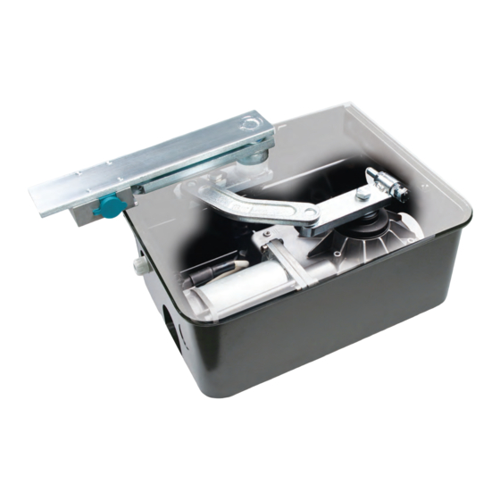
Page 4: Parts Diagram
PARTS DIAGRAM PARTS DIAGRAM WARNING - For Installation By Qualified Personnel Only. tem Description Part No. Cover I8CV Gate Attachment I8GATT Intermediate Drive Arm I8IDRAM Manual Release Mechanism I8LCKMN Manual Release Key I8MNRKY Secondary Drive Arm I8SDA Primary Drive Arm with Hardware I8PDRARM Gearmotor Assembly I8GMA... -
Page 5: Table Of Contents
TABLE OF CONTENTS TABLE OF CONTENTS Parts Diagram/Parts List ......... . .i Important Safety Information Important Safety Instructions . -
Page 6: Important Safety Information
IMPORTANT SAFETY INFORMATION IMPORTANT SAFETY INFORMATION WARNING - Not following these instructions may cause severe injury or death to persons. IMPORTANT SAFETY INSTRUCTIONS WARNING – To reduce the risk of severe injury or death: 1. READ AND FOLLOW ALL INSTRUCTIONS. 2. - Page 7 IMPORTANT SAFETY INFORMATION IMPORTANT SAFETY INFORMATION WARNING - Not following these instructions may cause severe injury or death to persons. IMPORTANT INSTALLATION INSTRUCTIONS Continued 6. Controls intended for user activation must be located at least six feet (6’) away from any mov- ing part of the gate and where the user is prevented from reaching over, under, around or through the gate to operate the controls.
-
Page 8: Maintenance/General Safety Precautions
IMPORTANT SAFETY INFORMATION IMPORTANT SAFETY INFORMATION WARNING - Not following these instructions may cause severe injury or death to persons. MAINTENANCE Remove the Power Harness from the Control Board (refer to page 17) • Clean and lubricate the turning pins and gate hinges using the recommended lubricant. •... -
Page 9: Terminology
IMPORTANT SAFETY INFORMATION IMPORTANT SAFETY INFORMATION CAUTION: To Reduce the Risk of Fire or Injury to Persons a) Use only the following type and size of battery(ies): Yuasa NP7-12 b) Do not dispose of the battery(ies) in fire. The cells may explode. Check with local codes for possible dis- posal instructions. -
Page 10: Photo Beam (Non-Contact Sensor) Installation
ruction IMPORTANT SAFETY INFORMATION IMPORTANT SAFETY INFORMATION Charger Charger Center Safety Radio Loop Loop Sensor Rec. Power Power WARNING - Not following these instructions may cause severe injury or death to persons. Low Battery Low Battery NOTE - This type of installation DOES NOT reverse the gate all the way back to its limits when the photo-beam Motor Sensor Check Motor is obstructed. -
Page 11: Edge Sensor (Contact Sensor) Installation
Low Battery Low Battery Motor Sensor Check Motor min. IMPORTANT SAFETY INFORMATION IMPORTANT SAFETY INFORMATION Hold Open Mag. Timer Lock WARNING - Not following these instructions may cause severe injury or death to persons. Open Edge Sensor (contact sensor) Installation N.C. -
Page 12: Audible Alarm Reset Switch Installation
IMPORTANT SAFETY INFORMATION IMPORTANT SAFETY INFORMATION WARNING - Not following these instructions may cause severe injury or death to persons. Audible Alarm Reset Switch Installation Manual Reset for the Audible Alarm UL325 standard requires an audible alarm to go off after two consecutive events detected by the primary entrapment protection of the gate operator (obstruction sensor). -
Page 13: Important Installation Information
IMPORTANT INSTALLATION INFORMATION IMPORTANT INSTALLATION INFORMATION CAUTION - FOR USE WITH GATES OF A MAXIMUM OF 12 FT IN LENGTH AND 650 LBS. IN WEIGHT. WARNING - TO REDUCE THE RISK OF SEVERE INJURY OR DEATH TO PERSONS: This is NOT a pedestrian gate operator Do NOT Install the gate operator to lift gates 12'-0"... -
Page 14: Plan Of Installation - Open Inside
PLAN OF INSTALLATION PLAN OF INSTALLATION The gate must be installed in a location so that enough clearance is supplied between the gate and adjacent structures when opening and closing to reduce the risk of entrapment. Swinging gates shall not open into public access areas. 13.46"... -
Page 15: Plan Of Installation - Open Outside
INSTALLATION DETAILS INSTALLATION DETAILS STEP 5 Prepare for the wiring using conduit suited for underground application. Route the the conduit to an above ground junction box. STEP 6 Run a flexible drain pipe from the Gate Operator to an area drain. Ensure that the pipe has proper Upper Hinge slope to prevent any water... - Page 16 GATE OPERATOR INSTALLATION GATE OPERATOR INSTALLATION STEP 9 Mount the Gearmotor on the chassis and secure it using the provided hardware. Verify the proper direction of the Gearhead depending on the opening direction. Opens Opens Left Right STEP 10 Install the Primary Drive Arm, lining up its slot with the flats on the Gearhead.
-
Page 17: Gate Operator Installation
GATE OPERATOR INSTALLATION GATE OPERATOR INSTALLATION STEP 13 Install the Gate Attachment to the Intermediate Drive Arm. Mount the gate on the hinge(s) and verify its alignment with the hinge(s) and Articulation Point. Weld the gate to the Gate Attachment. STEP 14 Lock the Manual Release Mechanism (so that the gate is engaged with the Gate Operator). -
Page 18: Step 8 Through 9 - Limit Switch Setup
GATE OPERATOR INSTALLATION GATE OPERATOR INSTALLATION Limit Setup Procedure STEP 16 Primary Drive Arm To adjust the closed position stop: Closed Position Adjustment Bolt Loosen both nuts on the Closed Position Adjustment Bolt. Adjust the Bolt to stop the gate’s closing at the proper position: •... -
Page 19: Opening/Closing Setup
GATE OPERATOR INSTALLATION GATE OPERATOR INSTALLATION Opening/Closing Setup: To have the gate operator slow down prior to reaching its limits use the following steps: 1. Setup the positive stops manually to obtain the desired open and closed positions. Slow 2. Allow the gate operator to run a full open and close cycle (from stop to stop) without Fast interruption. -
Page 20: Control Box Installation
CONTROL BOX INSTALLATION CONTROL BOX INSTALLATION WARNING - If the control box is not mounted properly it may fall, causing damage and/or injury. The control box weight is approximately 40 lbs. Be sure that the substrate being mounted to and the fasteners being used are appropriate to support the weight of the control box. -
Page 21: Electrical Installation (120/220 Vac)
ELECTRICAL INSTALLATION ELECTRICAL INSTALLATION Caution – Do not connect the power harness to the board until the installation is ready for verification. Power Harness The X-9 Gate Operator requires a single phase AC line to operate and charge the batteries. Auxiliary Power Connection. -
Page 22: Single Unit Connections
ELECTRICAL INSTALLATION – SINGLE UNIT ELECTRICAL INSTALLATION – SINGLE UNIT Single Unit Connections Connect the wires from the motor unit to the terminal block mounted next to the control board. Match wire colors to the terminal block. Match Colors Connect the wire harness to the “OPEN RIGHT”... -
Page 23: Master/Slave Connections
ELECTRICAL INSTALLATION – MASTER/SLAVE ELECTRICAL INSTALLATION – MASTER/SLAVE Master/Slave Connections A Master/Slave control board is available, when required, to run two gate operators in synchronous mode. Slave Limit Open Limit Close Slave Limit Open Limit Close Obstruction Overlap Delay Center Safety Radio Sensor... -
Page 24: Vehicular Loop Detector Installation
VEHICULAR LOOP DETECTOR INSTALLATION VEHICULAR LOOP DETECTOR INSTALLATION Note: Not all loops may be necessary for every installation. Check local regulations and accepted best- practice design requirements. Dimension A – 5’ for Single Gate Operator 6’ for Master/Slave Gate Operator Outside Inside Center... -
Page 25: Installation Guidelines
VEHICULAR LOOP DETECTOR INSTALLATION VEHICULAR LOOP DETECTOR INSTALLATION W W A A R R N N I I N N G G – – C C o o n n s s u u l l t t t t h h e e i i n n s s t t a a l l l l a a t t i i o o n n i i n n s s t t r r u u c c t t i i o o n n s s f f r r o o m m t t h h e e l l o o o o p p d d e e t t e e c c t t o o r r m m a a n n u u f f a a c c t t u u r r e e r r . . T T h h e e f f o o l l l l o o w w i i n n g g s s t t a a t t e e m m e e n n t t s s a a r r e e p p r r o o v v i i d d e e d d a a s s a a g g u u i i d d e e b b u u t t d d i i f f f f e e r r e e n n t t r r e e q q u u i i r r e e m m e e n n t t s s m m a a y y b b e e r r e e q q u u i i r r e e d d b b y y t t h h e e v v e e h h i i c c u u l l a a r r l l o o o o p p d d e e t t e e c c t t o o r r m m a a n n u u f f a a c c t t u u r r e e r r . -
Page 26: Accessory Connections
Fail min. Safe/Secure ACCESSORY CONNECTIONS ACCESSORY CONNECTIONS Hold Open Timer Brake Close Open Commands Stop Open Master/Slave Master/Slave Guard Station Guard Station Open Commands Open Commands Safety Connector Loop Connector Siren C35 C36 Obstruction Overlap Delay Charger Charger Center Safety Radio Sensor Connection Locations... -
Page 27: Radio Receiver; Hold Open Timer
ACCESSORY CONNECTIONS ACCESSORY CONNECTIONS Charger Charger Center Safety Radio Loop Loop Sensor Rec. Power Power Note: All controls are normally open. Radio Receiver Low Battery Low Battery Motor Sensor Check Motor When connecting the Radio Receiver carefully verify the proper connections. The maximum voltage that the control board provides for external accessories is the maximum voltage of the battery, which is about 28 volts. -
Page 28: Viking Electromagnetic Lock
Lock Kit) Green Black 24VDC White Loop Conne Radio Station N.O. N.C. This Magnetic Lock is an OPTIONAL ACCESSORY available Mag. Lock from Viking Access Systems. Please order part number VA- TECHNICAL SUPPORT 1 800 908 0884 Motor Sensor Low Battery... -
Page 29: Magnetic Lock; Solenoid Connection; Guard Station
ACCESSORY CONNECTIONS ACCESSORY CONNECTIONS Fail Magnetic Lock Safe/Secure External supply for the magnetic lock must Obstruction Overlap Delay Charger Charger be provided. This will prevent rapid drainage Center Safety Radio Sensor Loop Loop Sensor Rec. Power Power of the battery in the event of power failure. Low Battery Low Battery Relay Contact 10A-250VAC... -
Page 30: Special Features
SPECIAL FEATURES SPECIAL FEATURES Intelligent Obstruction Sensor (Primary Entrapment Protection) Obstruction Overlap Delay Center Safety Sensor Loop Loop Trim Pot Location (Single Unit Board shown) min. The Obstruction Sensor detects obstructions Turning the Trim Pot clockwise in the path of the traveling gate. The Trim increases the sensitivity. -
Page 31: Gate Overlap Setting
SPECIAL FEATURES SPECIAL FEATURES Gate Overlap Setting Setting the Overlap Delay Pot to “0” will cause the master and the slave units to open and close at the same time A Master/Slave control board is required to operate two gates with a single controller. Obstruction Overlap Delay Sensor... -
Page 32: Auto-Open Feature
SPECIAL FEATURES SPECIAL FEATURES Auto-Open Feature The Auto-Open feature in Viking Gate Operators enables the following functionality in the event of power failure: a) Open the gate in case of power failure (120 or 220 VAC). b) Keep the gate at the open position as long as the there is no power. c) Resume to normal operation when the power has been restored. -
Page 33: Optional Vikingblue Installation
OPTIONAL VIKING BLUE INSTALLATION OPTIONAL VIKING BLUE INSTALLATION Match up Match up Match up 1. Insert CD into host computer White Dots White Dots White Dots 2. Install MS ActiveSync (check your computer, it may already be installed communicate with a PDA or smart phone. Install Install Install... -
Page 34: Optionalsolar Panel Installation
OPTIONAL SOLAR PANEL INSTALLATION OPTIONALSOLAR PANEL INSTALLATION For Viking Vehicular Gate Operators Connect the Solar Panel Controller as shown. Solar Input Battery Input Load Input – – – Remove the existing Power Harness and use the power harness provided. – –... -
Page 35: Solar Panel Installation
*With a 80 Watt (24VDC) Panel System. 1. The greater capacity of the batteries, the longer the system will operate on cloudy days. 2. If more specific information is needed, please consult with Viking Access Systems. For more information regarding solar energy refer to http:/www.nrel.gov. -
Page 36: Troubleshooting
TROUBLESHOOTING TROUBLESHOOTING Gate does not run – Motor Sensor indicator comes ON Check all motor connections to Ensure that the motor Check that all motor cable be fully engaged. Refer to page connections are: connections, junctions and 18 and 19. extensions are properly a) Properly connected;... - Page 37 TROUBLESHOOTING TROUBLESHOOTING Gate does not open or close Check all motor connections to Check that the stop command be fully engaged. Refer to page is not active. Refer to page 8 13, 18 and 19. and 25. Check that the UL command Check that the vehicular loop Check that the radio command (photo beam and/or edge...
- Page 38 Viking Access Systems is continuously working hard to identify and design products that will appeal to the industry and it’s needs. As technology continues to advance, we have developed a completely efficient and intelligent line of gate operators to meet the changing demands.
- Page 39 (Master/Slave installation with overlap gates) • Built-in protection against lightning strikes or similar electrical surges • Inherent overload protection in the regulated power supply for external accessories with multiple devices of protection Viking Access Systems Phone 800.908.0884 Fax 949.753.1640 631 Wald Irvine, CA 92618 www.vikingaccess.com...
Need help?
Do you have a question about the i-8 and is the answer not in the manual?
Questions and answers