
Subscribe to Our Youtube Channel
Related Manuals for Viking Access Systems E-4


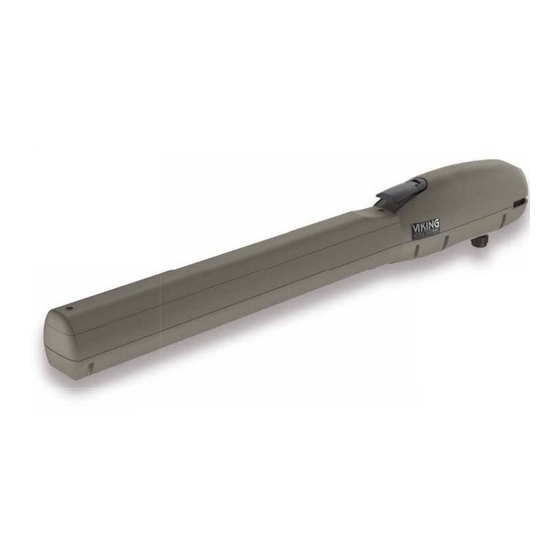
Summary of Contents for Viking Access Systems E-4
- Page 1 INSTALLATION INSTRUCTIONS AND SAFETY INFORMATION RESIDENTIAL CLASS I VEHICULAR SWING GATE OPERATOR...
- Page 2 The new E-4™ Residential Swing Gate Operator leads the industry in being the best, most cost e ective residential linear arm actuator. This new design allows for a maximum gate capacity up to 850 lbs/10’ or 550 lbs/16'. Featuring one Control Board for both Single and Dual gate applications, a convenient manual release handle and pre-wired for an easy and quick installation.
- Page 3 E-4 Vehicular Swing Gate Operator • Revision E4MN10.A1 • September 2018...
-
Page 4: Parts Diagram/Parts List
PARTS DIAGRAM - OPERATOR: Item Description Part No. Motor (24 VDC) E4MO Gearbox Chassis E4GBC Grease Cup E4GGC Casing Upper E4CU Lock & Keys, Manual Release E4LMR Key, Manual Release E4KEY Handle, Manual Release E4HMR Access Cover E4AC Level Assembly E4LA Limit Positive Stop E4LPS... -
Page 5: Operator References
PARTS DIAGRAM - CONTROLLER: Item Description Part No. ECU Cabinet Chassis (Standard) VNXECUBB Power Harness E4PH Battery Harness E4BTH Battery Switch DUMRS10 Battery DUBB12 Board Mounting Plate E4CBMP Plug-in Transformer PT24V1A EMI Board (optional) DUEMI10 Toroid Transformer - 10 amp (optional) DUTT10 Control Board VE4PCB... -
Page 6: Control Board References
CONTROL BOARD REFERENCES: DC IN DC IN Speed Speed Overlap Overlap Timer Timer Normal Normal Master Master Limit Open Limit Open Close Close Stop Stop Open Open Limit Close Limit Close Center Center Radio Radio ReOpen ReOpen Slave Slave Siren Siren Loop Loop... -
Page 7: Table Of Contents
TABLE OF CONTENTS: PARTS DIAGRAM/PARTS LIST PARTS DIAGRAM/PARTS LIST OPERATOR REFERENCES OPERATOR REFERENCES CONTROL BOARD REFERENCES CONTROL BOARD REFERENCES IMPORTANT SAFETY INFORMATION IMPORTANT SAFETY INFORMATION 6-12 6-12 Important Safety Instructions Important Installation Instructions Maintenance General Safety Precautions Operator Classification Secondary Entrapment Protection Requirements Secondary Entrapment Protection Installation Manual Release Audible Alarm Reset Installation... -
Page 8: Important Safety Information
IMPORTANT SAFETY INFORMATION WARNING! Not Following these instructions may cause severe injury or death. IMPORTANT SAFETY INSTRUCTIONS WARNING! To reduce the risk of severe injury or death. READ AND FOLLOW ALL INSTRUCTIONS . 2. Never let children operate or play with gate controls. Keep the remote away from children. -
Page 9: Important Installation Instructions
IMPORTANT SAFETY INFORMATION WARNING! Not Following these instructions may cause severe injury or death. IMPORTANT INSTALLATION INSTRUCTIONS (Continued) 7. The Stop and/or Reset button must be located in the line-of-sight of the gate. Activation of the reset control shall not cause the operator to start. 8. -
Page 10: Maintenance
IMPORTANT SAFETY INFORMATION WARNING! Not Following these instructions may cause severe injury or death. MAINTENANCE Remove the Power Harness from the Control Board. (refer to page 20) • Clean and lubricate the turning pins and gate hinges using the recommended lubricant. -
Page 11: Operator Classification
IMPORTANT SAFETY INFORMATION CAUTION: To Reduce the Risk of Fire or Injury to Persons: a. Use only the following type and size battery(ies): Yuasa NP7-12 or VIKING DUBA12 b. Do not dispose of the battery(ies) in fire. The cells may explode. Check with local codes for possible disposal instructions. -
Page 12: Secondary Entrapment Protection Requirements
IMPORTANT SAFETY INFORMATION WARNING! Not Following these instructions may cause severe injury or death. Monitored Entrapment Protection Requirements IMPORTANT: MONITORED PROTECTION MUST BE INSTALLED • REQUIRED BY UL 325, an approved MONITORED entrapment protection sensor is REQUIRED to be installed in all areas accessible to potential entrapment and pinch points. -
Page 13: Secondary Entrapment Protection Installation
IMPORTANT SAFETY INFORMATION WARNING! Not Following these instructions may cause severe injury or death. Cable use in Class 2 circuit to an external device shall be type CL2, CL2P, CL2R, CL2X or other cable with equivalent or better electrical, mechanical, and fl ammability ratings. Monitored Entrapment Protection Installation ! IMPORTANT: A minimum of one Monitored External Entrapment Sensor is required to be... -
Page 14: Audible Alarm Reset Installation
IMPORTANT SAFETY INFORMATION WARNING! Not Following these instructions may cause severe injury or death. Audible Alarm Reset Switch Installation Manual Reset for the Audible Alarm • UL325 standard requires an audible alarm to sound after two consecutive events detected by the primary entrapment protection of the gate operator (obstruction sensor). -
Page 15: Important Installation Information
IMPORTANT INSTALLATION INFORMATION CAUTION: To Reduce the Risk of Fire or Injury to Persons: WARNING: For use with gates at a maximum 850 lbs. in weight or 16 ft. in length. DO NOT allow pedestrian use of this gate DO NOT install the gate operator to lift gates Locate Control Buttons: 1. -
Page 16: Gate Operator Installation
GATE OPERATOR INSTALLATION Pull to Open Installation Option This application is typically used to open the gate towards the inside of the property. The operator will “ PULL” the gate to open. The gate must be installed in a location so that enough clearance is provided between the gate and adjacent structures to reduce the risk of entrapment when opening and closing. -
Page 17: Push To Open Installation
GATE OPERATOR INSTALLATION Push to Open Installation Option This application is typically used to open the gate towards the outside of the property. The operator will “ PUSH” the gate open. The gate must be installed in a location so that enough clearance is provided between the gate and adjacent structures to reduce the risk of entrapment when opening and closing. -
Page 18: Mounting The Gate Operator
Install the operator onto the mounting a. Dismount the operator. brackets. b. Complete the welding process. b. Manually Release the E-4 Operator. c. Lubricate the front bracket pivot point. Refer to page 11. d. Reinstall the gate operator and verify c. -
Page 19: Post Mounting Option
GATE OPERATOR INSTALLATION Post Mounting Option A Post Mount Kit is available for the E-4 Operator as an option to welding the operator Mounting Brackets to the gate and column. Part # VA-E4PSKT Mounting hardware provided for 3 1/2 ” round, 4” and 6” square posts. -
Page 20: Limit Switch Setup
The gate operator uses positive stops to set the limits. STEP 2 STEP 1 Remove the Lead Screw Cover: Manually Release the E-4 Operator: a. Remove the cover mounting screw. a. Lift the Release Handle. b. Remove the Lead Screw Cover. -
Page 21: Ecu Box Installation
ECU BOX INSTALLATION ! WARNING: If the control box is not mounted properly it may fall, causing damage and/or injury. The Electronic Control Unit (ECU) weight is approximately 40 lbs. Be sure that the substrate being mounted to and the fasteners being used are appropriate to support the weight of the control box. -
Page 22: Electrical Installation
ELECTRICAL INSTALLATION ! Caution: Always turn off power breakers when working with high voltage. DO NOT connect the “Power Harness” to the Control Board until the electrical installation is complete and ready for verification. To reduce the risk of electric shock, this equipment (external plug-in transformer) has a grounding type Plug, that has a third (grounding) pin. -
Page 23: Low Voltage Supply Option
ELECTRICAL INSTALLATION Low Voltage Supply Option As an alternative, the Control Board can be powered directly with 24VAC or 24VDC. The ECU may be equipped with a 24VAC plug-in transformer as the power supply. ! Caution: The DC Power Supply Input at the Control board is Polarity Sensitive. If supplying 24VDC directly to the Control Board, ensure correct DC polarity before you apply this power supply to the Control Board. -
Page 24: Motor Cable
ELECTRICAL INSTALLATION Motor Cable - Master (Single) NOTE: The position of the motor wires will dictate in which direction the motor will travel when given an open or close command. STEP 3 Master Motor: a. Connect motor wires to the “Master”... - Page 25 ELECTRICAL INSTALLATION Motor Cable - Master (Dual) DC IN DC IN Timer Timer Speed Speed Overlap Overlap Normal Normal Master Master Limit Open Limit Open Close Close Stop Stop Open Open Limit Close Limit Close Center Center Radio Radio ReOpen ReOpen Siren Siren...
-
Page 26: Control Board Setup
CONTROL BOARD SETUP Initial Settings “Speed” Motor Speed Increases or decreases the speed of “Overlap” gate travel. Overlap Delay Delays the gate from opening for Speed Speed the selected amount of time from 1-6 seconds. Normal Normal For Master/Slave or dual applications, the Master will delay to open and the slave will delay to close. -
Page 27: Initial Settings
Slave “MS” Used only for dual gate applications. Activating this feature will allow the Control Board to operate two E-4 gate operators for dual gate applications. See page 23. “Sync” Used only in conjunction with a barrier gate operator. Activating this feature allows for synchronized operation with a barrier gate operator. -
Page 28: Obstruction Detection Sensor (Ods)
CONTROL BOARD SETUP Obstruction Detection Sensor (ODS) ! IMPORTANT: The appropriate “ODS” setting is dependant upon the gate installation and con- struction. Set this feature accordingly. Additional Safety equipment should be used to reduce possible risk of injury or vehicle damage. When the Obstruction Sensor detects an obstruction it will: 1. -
Page 29: Accessory Connections
ACCESSORY CONNECTIONS Cable use in Class 2 circuit to an external device shall be type CL2, CL2P, CL2R, CL2X or other cable with equivalent or better electrical, mechanical, and flammability ratings. Radio Receiver Open-Stop-Close 1. By having the radio receiver connected as illustrated, every command of the radio transmitter will control the gate as follows: Every command of the radio transmitter will... -
Page 30: Open Commands, Guard Station
ACCESSORY CONNECTIONS Cable use in Class 2 circuit to an external device shall be type CL2, CL2P, CL2R, CL2X or other cable with equivalent or better electrical, mechanical, and flammability ratings. Guard Station TECHNICAL TIP: For more information regarding accessory connections and terminal functions, refer to “Appendix (A)”... -
Page 31: Viking Loop Rack
ACCESSORY CONNECTIONS Viking Loop Rack TECHNICAL TIP: This operator may be equipped with a pre-wired Loop Rack that plug-in type loop detectors can be connected to. This provides a convenient alternative to the box type loop detectors that would need to be wired to the control board. Viking does not provide either type of loop detectors. -
Page 32: Guidelines For Loop Installations
ACCESSORY CONNECTIONS Guidelines for Loop Installation 1. Prevent sharp corners in the geometry of the loop sensor. 2. Install the appropriate number of turns for your loop geometry based on the loop perimeter. Use Table C (below) as a guide. 3. -
Page 33: Magnetic Lock, Lock Solenoid
ACCESSORY CONNECTIONS Magnetic Lock, Lock Solenoid NOTE: Viking Access Systems does not provide external gate lock devices. These items can be purchased from your dealer or distributor. Power for the Locks: Do not use the 24VDC power supplied by Magnetic Lock the control board. -
Page 34: Barrier Arm Synchronization
BARRIER ARM SYNCHRONIZATION Barrier Arm Synchronization NOTE: The Control Board provides a convenient solution for applications that require synchronized operation with a Barrier Arm Operator. This type of application opens and closes in the following pattern: 1. Open Command is provided only to the Barrier Arm operator. 2. - Page 35 (THIS PAGE LEFT BLANK INTENTIONALLY) VIKING TECHNICAL SUPPORT 1.800.908.0884...
-
Page 36: Troubleshooting
TROUBLESHOOTING LED References The control board LEDs monitor the various circuits of the control board. Use the table below to identify the corresponding “TS Ref#” and refer to page 36 for further troubleshooting. DC IN DC IN Speed Speed Overlap Overlap Timer Timer... - Page 37 TROUBLESHOOTING Page 36 # LED Status Meaning TS Ref#(s) 1, 23 “Power” No power to control board or in Sleep Mode. SOLID Normal Condition. 1, 2 FLASHING Operator is running on batteries only. (pg 20-21) 10 “Low Bat” Normal Condition. 1, 2 SOLID Batteries are low.
-
Page 38: Solutions
TROUBLESHOOTING Solutions Begin the troubleshooting process by referring to the Status LEDs on the control board. Use pages 34-35 to identify the Troubleshooting Reference # (TS Ref#) then reference the table below. TS Ref# CHECK Page Ref# Check that the high voltage power supplied to “EMI Board” is within range. 100V-120V or 200V-240V. - Page 39 Appendix (A) Access Control Connections Power Connections The control board provides a 24VDC output to power external devices and controls. Alternatively, for devices that require a power supply other than 24VDC , the operators Power Box contains a convenient 120VAC receptacle to connect a plug-in transformer. Aux.
- Page 40 APPENDIX (A) Relays In General NOTE: Viking Access Systems does not provide the external safety devices and access controls. These items can be purchases from your dealer or distributor. In General Glossary of Terms 1. Terminal: Wire Connections. In regards to the Viking control board, 2.
- Page 41 Appendix (B) Cable use in Class 2 circuit to an external device shall be type CL2, CL2P, CL2R, CL2X or other cable with equivalent or better electrical, mechanical, and flammability ratings. Common Radio Receivers - Connections Multi-Code 1099 Grey Grey Radio Radio +28V...
- Page 42 Appendix (B) Omron E3K Center Center Cable use in Class 2 circuit to an external device shall be type CL2, CL2P, CL2R, CL2X or other cable with equivalent or better electrical, mechanical, and flammability ratings. ReOpen ReOpen ( - ) Power (+) Power Common Monitor Photoeye Connections NOTE: *...
-
Page 43: Viking Expansion Products
VIKING EXPANSION PRODUCTS VIKING MONITOR Off-site access to operator diagnostics and perform firmware updates from just about anywhere with cellular service. With the Viking App, this tool allows you to monitor and label multiple operators by site and location for quick reference. Provides error notifications, operator status, settings and diagnostic information. - Page 44 (THIS PAGE LEFT BLANK INTENTIONALLY) VIKING TECHNICAL SUPPORT 1.800.908.0884...
- Page 45 (THIS PAGE LEFT BLANK INTENTIONALLY) VIKING TECHNICAL SUPPORT 1.800.908.0884...
- Page 46 (THIS PAGE LEFT BLANK INTENTIONALLY) VIKING TECHNICAL SUPPORT 1.800.908.0884...
- Page 47 OUR CONTINUOUS COMMITMENT TO EXCELLENCE Viking Access Systems is continuously working hard to identify and design products that will appeal to the industry and its needs. As technology continues to advance, we have developed a completely e cient and intelligent line of gate operators to meet the changing demands.
- Page 48 V I K I N G AC C E S S S Y S T E M S 631 Wald Irvine, CA 92618 Phone 800.908.0884 Fax 949.753.1640 www.vikingaccess.com INSTALLATION DATE: NOTES: COMPANY / INSTALLER: CONTACT: SERIAL NUMBER(S): A L L I N S TA L L AT I O N , M A I N T E N A N C E A N D R E PA I R W O R K M U S T B E D O C U M E N T E D A N D M A D E AVA I L A B L E T O T H E U S E R .
Need help?
Do you have a question about the E-4 and is the answer not in the manual?
Questions and answers