
Related Manuals for Viking Access Systems X-390


Summary of Contents for Viking Access Systems X-390
- Page 1 INSTALLATION INSTRUCTIONS AND SAFETY INFORMATION S I N G L E A N D D UA L G AT E S Y S T E M S C L A S S I , C L A S S I I , C L A S S I I I , A N D C L A S S I V Residential and Commercial Vehicular Swing Gate Operator...
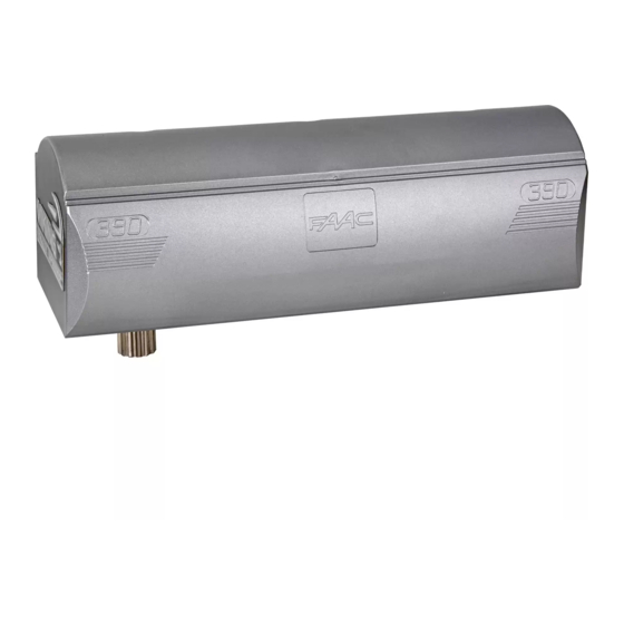
- Page 2 • Built-in motor heater for cold weather applications • Adjustable delay for overlapping dual gates • Equipped for 115/230 VAC, 24 VAC/VDC • Hold Open Timer to automatically close and Solar power supplies the gate THE VIKING X-390™ SWING GATE OPERATOR...
-
Page 3: Table Of Contents
Barrier Arm Synchronization Option TROUBLESHOOTING 36-41 LED References 36-37 LCD Display References 38-40 Solutions APPENDIX A PARTS DIAGRAM/PARTS LIST - OPERATOR PARTS DIAGRAM/PARTS LIST - CONTROLLER LIMITED WARRANTY 46-47 VIKING ACCESSORIES VIKING TECHNICAL SUPPORT 1.800.908.0884 X-390 • Rev A1 • October 2020... -
Page 4: Important Safety Information
IMPORTANT SAFETY INFORMATION WARNING! Not Following these instructions may cause severe injury or death. IMPORTANT SAFETY INSTRUCTIONS WARNING! To reduce the risk of severe injury or death. READ AND FOLLOW ALL INSTRUCTIONS . 2. Never let children operate or play with gate controls. Keep the remote away from children. -
Page 5: Important Installation Instructions
IMPORTANT SAFETY INFORMATION WARNING! Not Following these instructions may cause severe injury or death. IMPORTANT INSTALLATION INSTRUCTIONS (Continued) 7. The Stop and/or Reset button must be located in the line-of-sight of the gate. Activation of the reset control shall not cause the operator to start. 8. -
Page 6: Maintenance
IMPORTANT SAFETY INFORMATION WARNING! Not Following these instructions may cause severe injury or death. MAINTENANCE Remove the Power Harness from the Control Board. (refer to page 18) • Clean and lubricate the turning pins and gate hinges using the recommended lubricant. -
Page 7: Ul325 Gate Operator Classifications
IMPORTANT SAFETY INFORMATION WARNING! Not Following these instructions may cause severe injury or death. GENERAL SAFETY PRECAUTIONS (Continued) a. Use only the following type and size battery(ies): Yuasa NP7-12 or VIKING DUBA12 b. Do not dispose of the battery(ies) in fire. The cells may explode. Check with local codes for possible disposal instructions. -
Page 8: Monitored Entrapment Protection Requirements
IMPORTANT SAFETY INFORMATION WARNING! Not Following these instructions may cause severe injury or death. Monitored Entrapment Protection Requirements IMPORTANT: MONITORED PROTECTION MUST BE INSTALLED • REQUIRED BY UL 325, an approved MONITORED entrapment protection sensor is REQUIRED to be installed in all areas accessible to potential entrapment and pinch points. -
Page 9: Monitored Entrapment Protection Installation
IMPORTANT SAFETY INFORMATION WARNING! Not Following these instructions may cause severe injury or death. Monitored Entrapment Protection Installation ! IMPORTANT: A minimum of one Monitored External Entrapment Sensor is required to be connected to the UL terminal OR the Re-Open terminal. If there is a possible entrapment zone in the open direction, an external sensor MUST be wired to the “UL”... -
Page 10: Audible Alarm Reset Installation
IMPORTANT SAFETY INFORMATION WARNING! Not Following these instructions may cause severe injury or death. Audible Alarm Reset Switch Installation Manual Reset for the Audible Alarm • UL325 standard requires an audible alarm to sound after two consecutive events detected by the inherent entrapment protection of the gate operator (obstruction sensor). -
Page 11: Warning Placard Installation
IMPORTANT SAFETY INFORMATION WARNING! Not Following these instructions may cause severe injury or death. DO NOT allow pedestrian use of this gate DO NOT install the gate operator to lift gates Locate Control Buttons OPEN • Within sight of the gate, STOP CLOSE •... -
Page 12: Specifications
SPECIFICATIONS SPECIFICATIONS 15⅝ Max Gate Length 14 Feet 13½ Max Gate Weight 600 lbs UL 325 Classification Class I, II, III, IV *refer to page 5 Duty Cycle 100% Standard ECU Operating Voltage 24VDC 5¼ Main Power Source 120VAC / 240VAC Single Phase Main Power Current 1.5A / 1.0A (each motor) Main Power Frequency... -
Page 13: Control Board References
CONTROL BOARD REFERENCES 1. HEAT SINK - SECONDARY MODULE 13. M/S COMM CABLE CONNECTION - PRIMARY 24. FEATURE ACTIVATION TRIM POTS secures the control board and dissipates heat. Primary/Secondary (dual) gate applications. activate and set features. pg 24 pg 21 2. -
Page 14: Gate Operator Installation
GATE OPERATOR INSTALLATION Plans of Installation - Pull to Open Option This application is typically used to open the gate towards the inside of the property. The operator will “ PULL” the gate to open. The gate must be installed in a location so that enough clearance is provided between the gate and adjacent structures to reduce the risk of entrapment when opening and closing. - Page 15 GATE OPERATOR INSTALLATION Plans of Installation - Push to Open Option This application is typically used to open the gate towards the outside of the property. The operator will “ PUSH” the gate open. The gate must be installed in a location so that enough clearance is provided between the gate and adjacent structures to reduce the risk of entrapment when opening and closing.
-
Page 16: Installing The Gate Operator
GATE OPERATOR INSTALLATION Mounting the Gate Operator ! Caution: If the supplied Arm Pivot Bracket is not attached to a frame member that runs the full length of the gate, the gate operator may damage the gate. DO NOT attach the bracket to just a few pickets. -
Page 17: Limits Setup
GATE OPERATOR INSTALLATION Limits Setup STEP 1 Position the Limit Cams: 1. Position the gate to either the open or closed limit position. 2. Rotate the corresponding Limit Cam until the Limit Switch is engaged. The Limit Switch will “click” when engaged. TECHNICAL TIP: The Limit Cam can be rotated by hand with limited resistance and does not need to be tightened further. - Page 18 (THIS PAGE LEFT BLANK INTENTIONALLY) VIKING TECHNICAL SUPPORT 1.800.908.0884...
-
Page 19: Ecu Box Installation
ECU BOX INSTALLATION Mounting the ECU Box ! WARNING: If the control box is not mounted properly it may fall, causing damage and/or injury. The Electronic Control Unit (ECU) weight is approximately 40 lbs. Be sure that the substrate being mounted to and the fasteners being used are appropriate to support the weight of the control box. -
Page 20: Electrical Installation
ELECTRICAL INSTALLATION High Voltage Supply Option ! Caution: Always turn off power breakers when working with high voltage. DO NOT connect the “Power Harness” to the Control Board until the electrical installation is complete and ready for verification. STEP 1 ! WARNING: SINGLE PHASE AC ONLY At the “EMI Board”:... -
Page 21: Low Voltage Supply Option
ELECTRICAL INSTALLATION Low Voltage Supply Option TIP: As an alternative to high voltage, the operator can be powered by 24VAC. It is recommended to use Vikings Modular Power Box (part # VNXMPB) as the source. ! Caution: Always turn off power breakers when working with high voltage. DO NOT connect the “Power Harness”... -
Page 22: Motor Cable
ELECTRICAL INSTALLATION Motor Cable - Primary (Single) NOTE: The Single Electronic Control Unit is equipped to operate a single gate motor only, and does not include a Secondary Module. The steps described on page 21 do not apply for this type of application. STEP 3 Primary Motor: a. - Page 23 ELECTRICAL INSTALLATION Motor Cable - Secondary (Dual) NOTE: The Primary/Secondary, or Dual, Electronic Control Unit is equipped with both the VFlex Control Board (Primary) and a Secondary Module, both are required to operate two gate motors in tandem. STEP 5 STEP 6 Secondary to Primary Connections: Secondary Motor:...
-
Page 24: Monitored Ul Sensor Connections
ELECTRICAL INSTALLATION MONITORED UL SENSOR CONNECTIONS Re-Open (Monitored Input Terminal) (Monitored Input Terminal) The “UL” input terminal protects against The “Re-Open” input terminal protects entrapment in both the opening and against entrapment in the closing closing directions. Input will reverse direction ONLY. -
Page 25: Limits Indications
LIMIT INDICATIONS ! IMPORTANT: The gate operator uses positive stop limits. Therefore, the limits cannot be set electronically by this controller. The Limit Buttons on the control board have been rendered inactive by the controller. Refer to page 18 for specific instructions on how to set the limits for this gate operator.. -
Page 26: Control Board Setup
CONTROL BOARD SETUP Initial Settings “Speed” “ODS” Motor Speed Obstruction Detection Sensor Increases or decreases the speed of gate Sets the amount of force required to trip travel. the inherent obstruction sensor. See page 26 for more details about this feature. -
Page 27: Initial Settings
CONTROL BOARD SETUP Initial Settings NOTE: Installing a shunt, or jumper, on the pins will activate the feature. “Auto Open” - Power Failure Option Opens the gate automatically during power failure. Resumes normal operation when power is restored. Disabled when “Solar Mode” is ON. “Last Open”... -
Page 28: Obstruction Detection Sensor (Ods)
CONTROL BOARD SETUP Obstruction Detection Sensor (ODS) ! IMPORTANT: The appropriate “ODS” setting is dependant upon the gate installation and construction. Set this feature accordingly. Additional Safety equipment should be used to reduce possible risk of injury or vehicle damage. “ODS”... -
Page 29: Heater
CONTROL BOARD SETUP Viking Heater The operator has an integrated heater. Activate this feature when the operator is used in application temperatures down to -20°F (-29°C). Disabled when “Solar Mode” is ON. To set the heater to turn on at the Close Limit: HEATER 1. -
Page 30: Accessory Connections
ACCESSORY CONNECTIONS Access Control Connections Power Connections The control board provides a 24VDC output to power external devices and controls. “C” Common Terminals Connections and Input Functions: “N.O.” Normally Open Viking Terminal Function Device Terminal “+28V” --------------------- DC Positive --------------- “... -
Page 31: Access Control Connections
ACCESSORY CONNECTIONS Access Control Connections Relays In General Glossary of Terms 1. Terminal: Wire Connections. In regards to the Viking control board, all external safety devices and access 2. Input Terminal: On the Viking controls contain, and are, simple relays control board, the terminal which is that provide an input to the Viking labeled for a specific command (Re-... -
Page 32: Radio Receiver
ACCESSORY CONNECTIONS Radio Receiver NOTE: The ECU is supplied with FA-XR2C Radio Receiver and (2) FA-XT4RC Transmitters. STEP 1 Wire the Radio Receiver as illustrated. TECHNICAL TIP: The supplied Radio Receiver is IP44 rated for water resistance and can mounted Speed Speed Overlap... -
Page 33: Photocell
ACCESSORY CONNECTIONS Photocell N.O. N.O. Sync Sync NOTE: The ECU is factory equipped with a FA-XP30-10K Photocell. Refer to pages 6-7 for Auto Open Auto Open UL325 requirements. N.C. N.C. FA-XP30-10K Close Close Stop Stop Open Open Center Center ReOpen ReOpen +28V +28V... -
Page 34: Viking Loop Rack
ACCESSORY CONNECTIONS Viking Loop Rack TIP: This operator may be equipped with a pre-wired Loop Rack that plug-in type loop detectors can be connected to. This provides a convenient alternative to the box type loop detectors that would need to be wired to the control board. Viking does not provide either type of loop detectors. -
Page 35: Guidelines For Loop Installations
ACCESSORY CONNECTIONS Guidelines for Loop Installation 1. Prevent sharp corners in the geometry of the loop sensor. 2. Install the appropriate number of turns for your loop geometry based on the loop perimeter. Use the Table below as a guide. 3. -
Page 36: Magnetic Lock, Lock Solenoid
ACCESSORY CONNECTIONS Magnetic Lock, Lock Solenoid Lock Solenoid Magnetic Lock Power for the Locks: Do not use the 24VDC power supplied by the control board. A Class 2 external power supply or plug-in transformer, must be used for the magnetic lock or lock solenoid. -
Page 37: Barrier Arm Synchronization Option
ACCESSORY CONNECTIONS Barrier Arm Synchronization NOTE: The Control Board provides a convenient solution for applications that require synchronized operation with the Barrier Arm Operator. This type of application opens and closes in the following pattern: 1. Open Command is provided only to the Barrier Arm operator. 2. -
Page 38: Troubleshooting
TROUBLESHOOTING LED References In addition to the LCD Display, the control board LEDs monitor the various circuits of the control board. Use the table below to identify the corresponding “TS Ref#” and refer to pages 36-41 for further troubleshooting. Page 41 # LED Status Meaning... - Page 39 TROUBLESHOOTING Page 41 # LED Status Meaning TS Ref#(s) “C Loop” Normal Condition. 9, 10 SOLID An input from a device connected to the C Loop terminal. (pg 28, 32) 10 “Open” Normal Condition. 9, 10 SOLID An input from a device to Exit, Fire, Strike or Open terminal. (pg 28, 32) “STOP”...
-
Page 40: Lcd Display References
3. Press the Diagnose button to manually scroll through all of the Messages. Page 41 Meaning LCD MSG TS Ref #s MODEL Indicates the Model of the unit. X-390 X390 System Status Messages GATE IS Gate is stopped between limits. IDLE GATE IS Gate is opening. - Page 41 TROUBLESHOOTING LCD Display References Page 41 Meaning LCD MSG TS Ref #s RED CONN The Motor Connector is not plugged into the red Open Left or Open Right socket at the control board. (pg 11, 20) UNPLUGED Multi Meter Displays MOT AMP This is the motor current amperage during operation.
- Page 42 TROUBLESHOOTING LCD Display References Page 41 Meaning LCD MSG TS Ref #s Error Messages ERR AC Indicates that the 24VAC supply to the VFlex Board is too low from the 1, 3, 19 115/230 power supply. ERR AC Indicates that the 24VAC supply to the VFlex Board is too high from the 1, 3, 19 115/230 power supply.
-
Page 43: Solutions
TROUBLESHOOTING Solutions Begin the troubleshooting process by referring to the error messages on the LCD Display and/or the Status LEDs on the control board. Use pages 36-40 to identify the Troubleshooting Reference # (TS Ref#) then reference the table below. TS Ref# CHECK Page Ref# Check that the high voltage power supplied to “EMI Board”... - Page 44 9. When waking from sleep, there will be a 2 second delay before the motor responds to open or close. This will allow time for the safety devices to power up and stabilize. If more specific information is needed please consult with Viking Access Systems. For more information regarding solar energy refer to www.nrel.gov/solar...
- Page 45 (THIS PAGE LEFT BLANK INTENTIONALLY) VIKING TECHNICAL SUPPORT 1.800.908.0884...
-
Page 46: Parts Diagram/Parts List - Operator
PARTS DIAGRAM - OPERATOR: Item Description Part No. Protective Cover FA-727292 Limit Switch Cover LSC390 Limit Switch ( 1 ) and Cam ( 1 ) FA-390682 Limit Plate XLP390 Mounting Frame FA-722471 Motor/Gear Assembly FA-104579 Manual Release Key FA-713001 Positive Stop Assembly X390PSE Articulated Arm - Steel FA-7387051... -
Page 47: Parts Diagram/Parts List - Controller
PARTS DIAGRAM - CONTROLLER: Item Description Part No. Control Board - Primary VFLEXPCBU18 Motor Connector - Primary FAECUMCM39 Power Harness - Primary DUPHCECU Secondary Power Harness VECUSPH (Dual Controller only) Primary/Secondary Comm Cable VECUMSC (Dual Controller only) Secondary Module VFLEXSMU18 (Dual Controller only) Board Mounting Plate VECUBMP... -
Page 48: Limited Warranty
LIMITED WARRANTY FAAC International, Inc. (“Seller”) warrants the first Purchaser of the product to be free from defects in material and workmanship for a specific period as defined by the Warranty Disclosure on the website www.vikingaccess.com. The Warranty Period commences from the date of invoice. - Page 49 All products sold by the Seller are subject to design and/or appearance modifications, which are production standards at the time of shipment. The Seller may, but shall not be required to, modify or update products shipped prior to a current production standard. THIS WARRANTY IS EXPRESSLY IN LIEU OF ALL OTHER WARRANTIES EXPRESSED OR IMPLIED INCLUDING THE WARRANTIES OF MERCHANTABILITY AND FITNESS FOR USE.
-
Page 50: Viking Accessories
VIKING ACCESSORIES VIKING KONNECT Primary/Secondary Kit Secure and reliable Primary/Secondary communication between two single gate operators or ECU’s using Viking’s Konnect technology. Part# VA-KONNECT-MS ***Q -7 & ECU Operators require (2) Antenna Extension Cables (part# VA- RPSMA)*** *** NOT COMPATIBLE for Solar Mode setting on Control Board*** VIKING MONITOR Off-site access to operator diagnostics and perform firmware updates from just about anywhere with cellular service. - Page 51 OUR CONTINUOUS COMMITMENT TO EXCELLENCE Viking Access Systems is continuously working hard to identify and design products that will appeal to the industry and its needs. As technology continues to advance, we have developed a completely efficient and intelligent line of gate operators to meet the changing demands.
- Page 52 _ _ _ _ _ _ _ _ _ _ _ _ _ _ _ _ _ _ _ _ _ _ _ _ _ _ _ _ _ _ _ _ _ _ INSTALL ATION DATE: _ _ _ _ _ _ _ _ _ _ _ _ _ _ _ _ _ _ _ _ _ _ _ _ _ _ _ _ _ _ _ _ COMPANY / INSTALLER: _ _ _ _ _ _ _ _ _ _ _ _ _ _ _ _ _ _ _ _ _ _ _ _ _ _ _ _ _ _ _ _ _ _ _ _ _ _ _ _ _ _...
Need help?
Do you have a question about the X-390 and is the answer not in the manual?
Questions and answers