Table of Contents
Advertisement
Quick Links
dIXEL
XH240K
TEMPERATURE AND HUMIDITY CONTROLLER
1. GENERAL WARNING
1.1
PLEASE READ BEFORE USING THIS MANUAL
•
This manual is part of the product and should be kept near the instrument for easy and quick
reference.
•
The instrument shall not be used for purposes different from those described hereunder. It cannot
be used as a safety device.
•
Check the application limits before proceeding.
1.2
SAFETY PRECAUTIONS
•
Check the supply voltage is correct before connecting the instrument.
•
Do not expose to water or moisture: use the controller only within the operating limits avoiding
sudden temperature changes with high atmospheric humidity to prevent
condensation
•
Warning: disconnect all electrical connections before any kind of maintenance.
•
Fit the probe where it is not accessible by the End User. The instrument must not be opened.
•
In case of failure or faulty operation send the instrument back to the distributor or to "Dixell s.r.l."
(see address) with a detailed description of the fault.
•
Consider the maximum current which can be applied to each relay (see Technical Data).
•
Ensure that the wires for probes, loads and the power supply are separated and far enough from
each other, without crossing or intertwining.
•
In case of applications in industrial environments, the use of mains filters (our mod. FT1) in
parallel with inductive loads could be useful.
2. GENERAL DESCRIPTION
The XH240K is microprocessor controller suitable for applications on medium temperature
refrigerating units. It must be connected by means of a two-wire cable (∅ 1mm) at a distance of
up to 30 meters to the keyboard VH620, 100x64mm format. It controls both humidity and
temperature. It has 4 output relays to control compressor, heating elements , fan and humidifier.
It has 2 analogue inputs: one for temperature control, the other for humidity. There is one digital
input (free contact). An output allows the user to programme the parameter list with the "Hot
Key".
3. TEMPERATURE REGULATION
The temperature regulation is performed through neutral zone using compressor and heater
output relays.
ON
OFF
• Heating output: CUT IN is "SET_TEMP-dbt", CUT OUT is when the temperature reaches the
set point.
• Compressor output CUT IN is " SET_TEMP +dbt", CUT OUT is when the temperature
reaches the set point.
3.1 DEFROST
During the defrost temperature regulation is disabled.. Parameter "IdF" controls the interval
between defrost cycles, while its length is controlled by parameter "MdF".
To disable defrost set the MdF parameter to zero.
Humidity regulation, during defrost, depends on the Hud parameter. With
Hud=no humidity regulation is disabled during defrosts.
Hud=yES humidity regulation is performed also during defrosts.
4. HUMIDITY REGULATION
The humidity regulation is performed through neutral zone, by humidifying dehumidifying.
Humidity control can be disabled setting the SET_RH to "nu" value. In this case only the
temperature control is perform.
4.1 HUMIDIFYING ACTION
The humidifying action is done enabling the humidifier relay when the humidity is lower than the
"SET_RH-dbH" value.
The relay is disable when humidity reaches the set values.
4.2 DEHUMIDIFYING ACTION
The dehumidifying action is performed enabling the heating and compressor output together
when humidity is higher than SET_RH+dbH value.
1592002750 XH240K GB r1.0 15.06.2004 *
Operating instructions
formation of
Set point
Outputs are disabled when humidity comes back to the SET_RH value.
4.2.1 Relation between cooling, heating and dehumidifying
1.
If is simultaneously present a request of cooling (temp>SET_TEMP+dbt) and
dehumidifying (RH > SET_RH+dbH): the cooling action has the priority over the
dehumidifying action: only the compressor relay is energised till the SET_TEMP is
reached at this point also the heating relay is enabled.
2.
If is simultaneously present a request of heating (temp< SET_TEMP-dbt) and
dehumidifying (RH > SET_RH+dbH): the dehumidifying action has the priority over the
heating action: both the compressor and the heating relays are energised till the humidity
set is reached at this point only the heating relay is enabled.
5. FANS
The fan control mode is selected by means of the "FnC" parameter:
C-n = running when a load is on, OFF during the defrost;
C-y = running when a load is on, ON during the defrost;
O-n = continuous mode, OFF during the defrost;
O-y = continuous mode, ON during the defrost;
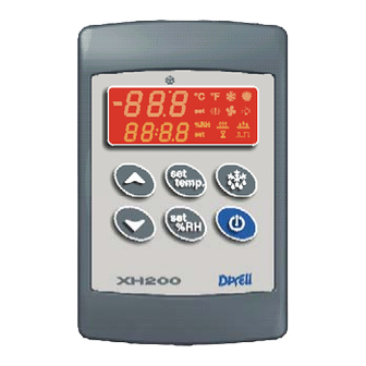
6. THE DISPLAY
KEY COMBINATIONS
+
To lock and unlock the keyboard
+
To enter the programming mode.
+
To exit the programming mode.
6.1 ICONS AND SYMBOLS
Each LED function is described in the following table.
Temperature Display
Humidity Display
LED
MODE
ON
Led 4
ON
ON
ON
FLASHING
ON
LED 3
FLASHING
LED 3
LED 2
FLASHING
ON
FLASHING
(temp)
XH240K
To
display
temperature set point. (SET_TEMP)
To display and modify target humidity
set point (SET_RH); in programming
mode it selects a parameter or confirm
an operation.
In programming mode it browses the
parameter codes or increases the
displayed value.
In programming mode it browses the
parameter codes or decreases the
displayed value.
By holding it pressed for 3s the defrost
Switch ON and OFF the instrument.
LED2
LED3
LED4
FUNCTION
- ALARM signal
- Instrument in stand by.
- In "Pr2" indicates that the parameter is also present in "Pr1".
°C
The compressor is running
- Anti-short cycle delay enabled
The defrost is enabled
Drip time in progress
Programming Phase (flashing with LED3)
Heating enabled
Temperature Set programming phase
1592002750
and
modify
target
is started..
1/4
Advertisement
Table of Contents

Subscribe to Our Youtube Channel
Related Manuals for dixell XH240K


Summary of Contents for dixell XH240K
-
Page 1: Operating Instructions
Fit the probe where it is not accessible by the End User. The instrument must not be opened. In programming mode it browses the • In case of failure or faulty operation send the instrument back to the distributor or to “Dixell s.r.l.” parameter codes or increases the (see address) with a detailed description of the fault. - Page 2 “did” interval, before signalling the alarm event (I2F= PAL). than SET_TEMP -dbt value and disabled when the SET_TEMP is reached. If the nPS activation in the “did” time is reached, switch off and on the instrument to restart normal regulation. 1592002750 XH240K GB r1.0 15.06.2004 * XH240K...
- Page 3 9. INSTALLATION AND MOUNTING The XH240K shall be mounted in a panel with two or more screws and it must be connected to NOTE the message “Err” is displayed for failed programming. In this case turn the unit off and the keyboard by means of a two-wire cable (∅...
- Page 4 ≤ Pr1 Low humidity alarm setting 0 ÷ 50 / Lci ÷ AHu Power supply: from XH240K; Display: double display + icons. Pr1 High humidity alarm setting 0 ÷ 50 / AHL ÷ uci Optional output: buzzer Pr2 Humidity alarm recovery differential 0.5 ÷...
Need help?
Do you have a question about the XH240K and is the answer not in the manual?
Questions and answers