dixell iCHILL IC200CX Series User Manual
Hide thumbs
Also See for iCHILL IC200CX Series:
- Quick reference manual (58 pages) ,
- Quick reference manual (40 pages)
Table of Contents
Advertisement
Quick Links
Advertisement
Table of Contents

Subscribe to Our Youtube Channel
Related Manuals for dixell iCHILL IC200CX Series


Summary of Contents for dixell iCHILL IC200CX Series
- Page 1 IC200CX Series User manual...
- Page 2 INDEX GENERAL ADVICE GENERAL FEATURES MAIN FUNCTION IC200 CX TABLE OF THE FEATURES USER INTERFACE DISPLAY CONFIGURATION FORCED READ - OUT OF THE TOP AND BOTTOM DISPLAY ICONS MEANING MEANING / FUNCTIONNING OF THE BOTTOM DISPLAY LED DISPLAY LAYOUT HOW TO READ THE MEASUREMENT LIST READ PROBE VALUES OF CIRCUIT 1 OR 2 DISPLAY INFORMATION READ THE SET POINT VALUE...
- Page 3 FUNCTION MENU “ M” KEY 12.1 ALARM LIST: SHOW AND RESET 12.2 COMPRESSOR OVERLOAD ALARM RESET 12.3 COMPRESSOR OVERLOAD PASSWORD. 12.4 ALARM LOG LIST 12.5 ERASE THE ALARM LOG LIST 12.6 PASSWORD VALUE OF THE ALARM LIST 12.7 DISABLE – ENABLE A SINGLE CIRCUIT 12.8 READ-OUT OF A CIRCUIT NOT ENABLED 12.9...
- Page 4 PUMP DOWN 23.1 OFF UNIT WITH PUMP DOWN AND WITH LOW PRESSURE SWITCH CONTROL 23.2 PUMP DOWN WITH DEDICATED PRESSURE SWITCH 23.3 PUMP DOWN FUNCTION WITH DEDICATED PRESSURE PROBE 23.4 PUMP DOWN ALARM DURING COMPRESSORS START- UP 23.5 PUMP DOWN ALARM DURING COMPRESSORS SWITCHING OFF 23.6 PUMP DOWN BY DELAY TIME UNLOADING...
- Page 5 33.10 END DEFROST BY LOW WATER OUTLET EVAPORATOR TEMPERATURE 33.11 DEFROST PARAMETER DESCRIPTION ENERGY SAVING 34.1 ENERGY SAVING: DIGITAL INPUT ACTIVATION 34.2 ENERGY SAVING TIME TABLE WITH RTC 34.3 RTC DAILY TIME TABLE PROGRAMMING 34.4 ENERGY SAVING OR UNIT ON/OFF ACTIVATION WITH RTC PROGRAMMING 34.5 UNIT ON/OFF ACTIVATION WITH RTC PROGRAMMING AND DIGITAL INPUT DYNAMIC SETPOINT...
- Page 6 39.42 KEYABOARD ALARM AUTOMATIC TO MANUAL ALARM PROCEDURE TABLE OF THE OUTPUT STATUS IN ALARM CONDITION 41.1 ALARM: “A” TYPE AND STATUS OF THE LOADS IN CASE OF ALARM 41.2 ALARM: “B” TYPE AND STATUS OF THE LOADS IN CASE OF ALARM 41.3 ALARM: “C”...
- Page 7 • The instrument must not be opened. • In case of failure or faulty operation send the instrument back to the distributor or to “Dixell s.r.l.” (see address) with a detailed description of the fault. • Consider the maximum current which can be applied to each relay (see thechnical Data).
- Page 9 1592022700 User manual iCHILL 200CX Rel. 1.0 22/04/2009 GENERAL FEATURES iCHILL IC200CX is an electronic controller for chiller unit applications having one or two circuits: • Air/air • Air/water • Water/water • Motocondensing Additional features: • Heat pump with gas reversibility •...
- Page 10 Internal Data logger up to 100 events Supervisor / tele assistance/ monitoring • TTL output for XJ485CX interface (ModBus protocol) for Dixell monitoring system for local and remote control Up to 2 remote terminals • With NTC ambient temperature probe...
- Page 11 1592022700 User manual iCHILL 200CX Rel. 1.0 22/04/2009 3 IC200 CX TABLE OF THE FEATURES CHARACTERISTICS IC206CX IC208CX N° KEYS RELAYS DIGITAL INPUTS Config Config ANALOG INPUTS 4 NTC – PTC Config Config 2 NTC - PTC - 4÷20mA - 0 ÷ 5Volt PROPORTIONAL OUTPUTS 2 configurables (signal 0÷10V) Config...
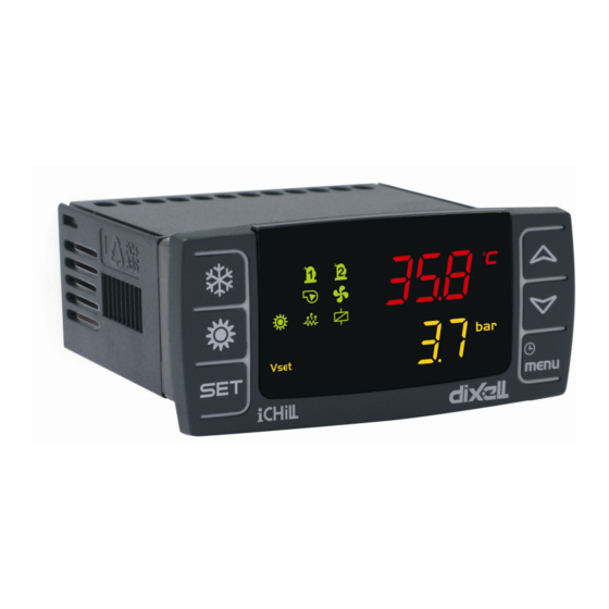
- Page 12 1592022700 User manual iCHILL 200CX Rel. 1.0 22/04/2009 4 USER INTERFACE 4.1 DISPLAY CONFIGURATION IC 206CX / IC 208CX Remote keyboard...
- Page 13 1592022700 User manual iCHILL 200CX Rel. 1.0 22/04/2009 Main display (upper display) Parameters dP01 (IC200CX), dP05 (remote keyboard n° 1), dP07 (remote keyboard n° 2) PARAMETER CORRESPONDING DESCRIPTION VALUE LABEL No display read out No label NTC temperature probe of the evaporator water inlet Out1 circuit 1 NTC temperature probe of the evaporator water outlet 1 and 2 Out2 circuit 2...
- Page 14 1592022700 User manual iCHILL 200CX Rel. 1.0 22/04/2009 PARAMETER CORRESPONDING DESCRIPTION VALUE LABEL No label No display read out NTC temperature probe of the evaporator water inlet Out1 circuit 1 NTC temperature probe of the evaporator water outlet 1 and 2 Out2 circuit 2 NTC temperature probe of the common evaporator water outlet Eout...
- Page 15 1592022700 User manual iCHILL 200CX Rel. 1.0 22/04/2009 • Condenser probe temperature Cdt1 / pressure CdP1 Bottom display of the circuit 1 • Evaporator pressure probe LP1 Top display of the circuit 2: Condenser probe temperature Cdt2 / pressure CdP2 Bottom display of the circuit 2 Evaporator pressure probe LP2 4.3 I...
- Page 16 1592022700 User manual iCHILL 200CX Rel. 1.0 22/04/2009 4.4 M EANING UNCTIONNING OF THE BOTTOM DISPLAY LED Led # 1 – 2 (With RTC) If the bottom display shows the RTC the leds are both blinking. Led # 1 – 2 In function Menu During the time counting to the next defrost for one or both circuits the leds are both blinking.
- Page 17 1592022700 User manual iCHILL 200CX Rel. 1.0 22/04/2009 6 DISPLAY INFORMATION 6.1 R EAD THE OINT VALUE Push and release the SET key, the set value is displayed. In stand-by the bottom display shows SetC (set chiller), by pushing SET again the next label is SetH (set heat pump). If the unit is running the only set displayed is related to the running mode.
- Page 18 1592022700 User manual iCHILL 200CX Rel. 1.0 22/04/2009 6.5 D STD-BY ISPLAY ISUALIZATION IN It is possible to customise the visualization of the display when the unit is in STD-BY: Parameter dP4: 0= the display shows "STD-BY" 1= the display shows what defined by parameters dP1 and dP2 2= the display shows “OFF”...
- Page 19 1592022700 User manual iCHILL 200CX Rel. 1.0 22/04/2009 6.7 KEY FUNCTION ACTION FUNCTION Push and release Show chiller set point SetC and heat pump SetH In chiller or heat pump if the Energy saving or the Dynamic Push once again setpoint are enabled it shows the real setpoint Setr, the led is blinking.
- Page 20 1592022700 User manual iCHILL 200CX Rel. 1.0 22/04/2009 7 REMOTE TERMINAL The iCHILL can be connected to a remote keyboard (max 2 remote keyboards). The remote keyboard with probe on board can be used for the regulation of the machine. The maximum length of the cable is 150mt (shielded cable is recommended).
- Page 21 1592022700 User manual iCHILL 200CX Rel. 1.0 22/04/2009 9 ANALOG AND DIGITAL OUTPUT CONFIGURATION 9.1 A 1 - P 2 – P 5 – P NALOG INPUT Parameters involved: CF08 = Configuration PB1 CF09 = Configuration PB2 CF12 = Configuration PB5 CF13 = Configuration PB6 Not enabled Temperature probe PTC for compressor #1 discharge...
- Page 22 1592022700 User manual iCHILL 200CX Rel. 1.0 22/04/2009 Flow switch evaporator pump / supply fan overload Flow switch condenser pump Antifreeze heater circuit 1 Antifreeze heater circuit 2 High pressure switch circuit 1 High pressure switch circuit 2 Low pressure switch circuit 1 10.
- Page 23 1592022700 User manual iCHILL 200CX Rel. 1.0 22/04/2009 Part Winding 1 of the compressor 2 34. Part Winding 2 of the compressor 2 35. Capacity step valve 1 compressor 2 36. By-pass gas valve compressor 2 start 9.5 A 0 ÷ 10 V (OUT1 OUT2) NALOG OUTPUT CONFIGURATION...
- Page 24 1592022700 User manual iCHILL 200CX Rel. 1.0 22/04/2009 10 PROGRAMMING WITH THE “HOT KEY 64” 10.1 D “H ” OWNLOAD HOW TO PROGRAM AN INSTRUMENT WITH A PROGRAMMED 1. Turn off the instrument supply 2. Insert the hot key. 3. Turn on the power supply. 4.
- Page 25 1592022700 User manual iCHILL 200CX Rel. 1.0 22/04/2009 Change the value with UP or DOWN keys; Push “SET” to confirm, after some seconds the display shows the next parameter; Exit: Push SET + UP together when a parameter label is displayed or wait 15seconds without pushing a key. NOTE: a new parameter value is confirmed also after the 15 seconds of timeout is expired (without pushing SET key to confirm).
- Page 26 1592022700 User manual iCHILL 200CX Rel. 1.0 22/04/2009 Push SET key and the top display shows a blinking 0, with UP or DOWN insert the Pr2 password. Push SET and, if the value is correct, top display will show the first family of parameters “ALL”. Otherwise set the password again. Select a parameter family with DOWN or UP keys.
- Page 27 1592022700 User manual iCHILL 200CX Rel. 1.0 22/04/2009 Push 1 time the DOWN key and the led 3 should be on, the parameter is now available in Pr1. To hide the parameter in Pr1: Keep pushed SET key; Push 1 time the DOWN key and the led 3 should be off, the parameter is now removed from Pr1. 11.9 M OVE A PARAMETER FROM Enter Pr3 programming level, here the parameter are all visible:...
- Page 28 1592022700 User manual iCHILL 200CX Rel. 1.0 22/04/2009 11.12 HANGE THE POLARITY OF THE DIGITAL NPUTS UTPUTS Enter the programming: Select a parameter with digital input/output value, the top display shows the label o before the configuration number while the bottom display shows the parameter label.
- Page 29 1592022700 User manual iCHILL 200CX Rel. 1.0 22/04/2009 12.3 C OMPRESSOR OVERLOAD PASSWORD The default value is 0; to change this value enter Pr3 level, search AL60 parameter and modify its value. 12.4 A LARM LOG LIST ALOG FUNCTION TO SEE THE ALARM LOG The function and the alarm codes are visible only if there are alarm events.
- Page 30 1592022700 User manual iCHILL 200CX Rel. 1.0 22/04/2009 12.10 OUT OF A COMPRESSOR OT ENABLED During the normal running condition a disabled compressor is displayed with a blinking label alternated with the measurement value of the display. If the compressor is disabled these the corresponding labels: C1dS = compressor 1 disabled, C2dS = compressor 2 disabled The label C1dS…C2dS are available only if the corresponding compressor is configured.
- Page 31 1592022700 User manual iCHILL 200CX Rel. 1.0 22/04/2009 Cond FUNCTION selects the proportional output 1 and 2. Label involved in Cond function. Cnd1 Proportional output status of the condenser fan of the circuit 1. Cnd2 Proportional output status of the condenser fan of the circuit 2. TO SEE THE OUTPUT PERCENTAGE: Enter the function menu Cond...
- Page 32 1592022700 User manual iCHILL 200CX Rel. 1.0 22/04/2009 Select with UP or DOWN the trEM function Push SET the trE1 or trE2 label is shown on the bottom display, the top display shows the probe value. Use the UP or DOWN arrow to change beteween trE1 or trE2 read-out. To exit to the normal display read-out push MENU or wait the time –...
- Page 33 1592022700 User manual iCHILL 200CX Rel. 1.0 22/04/2009 CF51 = 1 External air temperature probe > St12+ ST13 the unit starts in chiller, External air temperature probe < ST12 the unit starts in heat pump. 14 UNIT START - STOP The unit start sotp can be done from one of the following operations: •...
- Page 34 1592022700 User manual iCHILL 200CX Rel. 1.0 22/04/2009 With active contact if the unit is being switched off by keyboard it can be switched on by keyboard. If the unit is being switched off by keyboard, in order to switch on the unit from digital input it must be deactivated and activated. 14.6 MODE WITH DIGITAL INPUT CONFIGURATED AS HEAT PUMP REQUEST Unit configured as motocondensing CF03 = 1...
- Page 35 1592022700 User manual iCHILL 200CX Rel. 1.0 22/04/2009 To have the same regulation both for chiller and heat pump set the parameters ST09 and ST10 with the same value 16 THERMOREGULATION: PROPORTIONAL OR NEUTRAL ZONE Par. ST11 determines the type of regulation 0= Proportional 1= Neutral zone 16.1 G...
- Page 36 1592022700 User manual iCHILL 200CX Rel. 1.0 22/04/2009 Compressor regulation in heat pump 17 COMPRESSOR STATUS INTO THE NEUTRAL ZONE A particular functioning is scheduled thruogh the rotation or the forced insertion of compressors or spteps during the loads functioning into the neutral zone Par.
- Page 37 1592022700 User manual iCHILL 200CX Rel. 1.0 22/04/2009 17.1 MAXIMUM TIME OF NEUTRAL ZONE STAY WITHOUT INSERTION OF RESOURCES WITH AT LEAS ONE RESOURCE INSERTED Par. CO50 With at least one compressor on, when the functioning is into the neutral zone, is calculated the time set by the par. CO50 after which is forced a compressor or partialization step insertion.
- Page 38 1592022700 User manual iCHILL 200CX Rel. 1.0 22/04/2009 When both compressors are activeted the thermoregulation is done with the variation of the capacity percentage. When the thermoregulation switches off the ON/OFF compressor, the controller manages the capacity percentage to follow the real request.
- Page 39 1592022700 User manual iCHILL 200CX Rel. 1.0 22/04/2009 When the thermoregulation requests the activation of the second compressor. When both compressors are activated the thermoregulation is done with the variation of the capacity percentage. When the thermoregulation switches off the ON/OFF compressor, the controller manages the capacity percentage to follow the real request.
- Page 40 1592022700 User manual iCHILL 200CX Rel. 1.0 22/04/2009 18 THERMOREGULATION AND COMPRESSORS ROTATION The CO13 parameter allows to choose the sequence of activation of the compressors. CO13= 0 Sequential. Depending on the thermoregulation: Activation sequence: COMP. 1 COMP.2 Deactivation sequence: COMP.2 COMP.1 CO13= 1 Rotation by hour.
- Page 41 1592022700 User manual iCHILL 200CX Rel. 1.0 22/04/2009 20.4 P INDING This algorithm allows to reduce the start-up current when using hermetic or semi-hermetic compressors or medium – big screw compressors. Each compressor needs two relay outputs: • One is the PW motor coil 1 of the compressor; •...
- Page 42 1592022700 User manual iCHILL 200CX Rel. 1.0 22/04/2009 1= the steps are turned on in sequential mode, the outputs are anabled or disabled depending on the output polarity. In case of thermoregulation request one of the step is turned on or off while the other steps do not change their status. Eg: 1 capacity compressor with 3 partializations: 4 Power steps.
- Page 43 1592022700 User manual iCHILL 200CX Rel. 1.0 22/04/2009 Having one compressor with 3 partializations, at the compressor start-up, with CO07=0, the partialization valve is enabled only for the time CO12 but it won’t be never used during the thermoregulation. After the compressor stops running the time CO12 will be reloaded. Having one compressor with 3 partializations, at the compressor start-up, with CO07=1, the partialization valve is enabled for the time CO12 and it will be considered also as thermoregulation step.
- Page 44 1592022700 User manual iCHILL 200CX Rel. 1.0 22/04/2009 If the last compressor stops before the low pressure switch because of the CO33 time-out (maximum compressor on time after turning off the P.D. solenoid valve), the ICHILL calculates the AL28 parameter (maximum number of pump down alarm per hour) and if an alarm occurs the display will show the alarm code, the buzzer and the alarm relay will be on.
- Page 45 1592022700 User manual iCHILL 200CX Rel. 1.0 22/04/2009 If the last compressor stops before the pump down pressure switch because of the CO33 time-out (maximum compressor on time after turning off the P.D. solenoid valve), the ICHILL calculates the AL28 parameter (maximum number of pump down alarm per hour) and if an alarm occurs the display will show the alarm code, the buzzer and the alarm relay will be on.
- Page 46 1592022700 User manual iCHILL 200CX Rel. 1.0 22/04/2009 It is possible to have the pump down procedure also without pressostat or pressure trasducers ; in this case, by configuring CO52 and CO53, the compressor is switched off after CO52 time starting from pump down valve activation and switched on after CO53 time starting from pump down valve deactivation.
- Page 47 1592022700 User manual iCHILL 200CX Rel. 1.0 22/04/2009 24.6 R EGULATION IN HEAT PUMP MODE UNLOADING IN HEAT PUMP MODE The compressor unloading in heat pump mode is managed by the analogue input configured as evaporator probe circuit 1 or 2. When the heat pump thermoregulation request begins to start the compressors, if the evaporator pressure/temperature is equal or lower than CO43 setpoint the unloading process, of that circuit probe, is engaged.
- Page 48 1592022700 User manual iCHILL 200CX Rel. 1.0 22/04/2009 When the unit is in stand-by or remote off and the parameter Ar21=1, if the antifreeze thermoregulation requires the water pump is turned on. CO15 = 4: modulating control type 1. The water pump/ supply fan are running only if the unit is running (in chiller or heat pump). After giving the start in chiller or heat pump mode the compressor regulation starts only after the time delay CO16.
- Page 49 1592022700 User manual iCHILL 200CX Rel. 1.0 22/04/2009 Note: During the defrost and when the compressor is off in dripping time the pump is on. 28 WATER PUMP OF THE CONDENSER 28.1 C ONDENSER ATER PUMP CONTROL Operative mode of the condenser water pump CO20 = 0 Not enabled, pump not controlled.
- Page 50 1592022700 User manual iCHILL 200CX Rel. 1.0 22/04/2009 29.2 C ONDENSER ATER UMP ROTATION THROUGH DIGITAL INPUT CONTROL With two digital inputs configured as overload alarm of water pump and support pump the rotation is enabled when the digital input of the running pump becomes active.
- Page 51 1592022700 User manual iCHILL 200CX Rel. 1.0 22/04/2009 Modulating control of the condenser pump in Chiller mode: Modulating control of the condenser pump in Heat pump mode: 31 CONDENSER FAN REGULATION With the parameters CF43..CF46 is possible to select the analog output (OUT1..OUT4) and the signal to manage the condenser fan in proportional mode.
- Page 52 1592022700 User manual iCHILL 200CX Rel. 1.0 22/04/2009 Par. FA01 = 1 + Par. FA02 = 1 Independent from the compressor status but off in stand–by. Par. FA01 = 2 + Par. FA02 = 0 Fans on, with ON/OFF regulation and with temperature/pressure transducer control, only when the compressor is on (at least one relay is configured as fan control).
- Page 53 1592022700 User manual iCHILL 200CX Rel. 1.0 22/04/2009 31.4 G RAPH ROPORTIONAL REGULATION OF CONDENSER FANS 31.5 G : ON / OFF RAPH REGULATION OF THE CONDENSER FAN HILLER 31.6 G : ON / OFF RAPH REGULATION OF THE CONDENSER FAN Pg.50/114...
- Page 54 1592022700 User manual iCHILL 200CX Rel. 1.0 22/04/2009 32 THERMOREGULATION OF THE ANTI FREEZE, INTEGRATION HEATING OR BOILER 32.1 T HERMOREGULATION OF THE HEATERS IN CHILLER The Par. Ar06 selects the probe/s control for the anti-freeze relay outputs configured as anti-freeze / support / boiler heaters for the circuits 1 and 2 in chiller mode.
- Page 55 1592022700 User manual iCHILL 200CX Rel. 1.0 22/04/2009 Par. Ar08 = 2: the heater 1 regulation is executed through the condenser water outlet NTC probe of the circuit 1. The heater 2 regulation is executed through the condenser water outlet NTC probe of the circuit 2. ATTENTION It is not possible to control the heaters of the circuit 1 with the NTC probe of the condenser water outlet of the circuit 2 and viceversa.
- Page 56 1592022700 User manual iCHILL 200CX Rel. 1.0 22/04/2009 33 DEFROST CYCLE The defrost cycle starts only if all these steps are determined: Heat pump unit DF01≠0 (defrost enabled) The condenser/evaporator probe is configured (per circuit) (if the evaporator probe/s is/are defined, the defrost cycle is always controlled by it / them).
- Page 57 1592022700 User manual iCHILL 200CX Rel. 1.0 22/04/2009 dF22=0 not possible (ACF1) not possible (ACF1) dF22=1 dF22=2 not possible (ACF1) not possible (ACF1) ATTENTION: The configuration error ACF1 is displayed if the parameter value of dF22 and dF23 is not permitted. 33.7 A UTOMATIC DEFROST PROCEDURE Phase 1: when the unit is working in heat pump mode and at least one compressor is running, if the condensing-evaporating...
- Page 58 1592022700 User manual iCHILL 200CX Rel. 1.0 22/04/2009 33.8 O THER NFORMATION ABOUT THE DEFROST If the unit is configured with one condenser see parameter FA05: 0= common condenser; 1= separated condensers. For FA05=0, common condenser, the defrost of the two circuits starts at the same time. ATTENTION Before starting the 3 phase, the dF06 counting (time delay between two circuits defrost) must be expired.
- Page 59 1592022700 User manual iCHILL 200CX Rel. 1.0 22/04/2009 dF06 defrost delay time between the 1 and the 2 circuit. After the interval dF09 determined by the defrost request of one of the circuits the other 2 circuits must wait also the time dF06 before defrosting.
- Page 60 1592022700 User manual iCHILL 200CX Rel. 1.0 22/04/2009 dF26 Stop supply fan during defrost cycle 0= Not enabled 1= Enabled dF26 Probe selection for minimum temperature outlet during defrost This parameter allows to select which probe controls the outlet temperature to force the exit of the defrost dF27 Set point for minimum temperature outlet during defrost 34 ENERGY SAVING 34.1 E...
- Page 61 1592022700 User manual iCHILL 200CX Rel. 1.0 22/04/2009 Example of a daily programming: Monday Enater parameter programming In the ES parameter family, select the parameter ES07, the top display shows 0 - 0 Push SET key: the top display shows 0 - 0 blinking, with UP or DOWN keys select the corresponding function (see next table) : Push SET to confirm.
- Page 62 1592022700 User manual iCHILL 200CX Rel. 1.0 22/04/2009 35 DYNAMIC SETPOINT The dynamic setpoint allows to increase or decrease the setpoint with a proportional value determined by Sd01 (chiller) and Sd02 (Heat pump) that depends from the 4..20mA analogue input or from the external air temperature probe. This function allows to save energy or run the unit when the external ambient is not within the normal operative conditions.
- Page 63 1592022700 User manual iCHILL 200CX Rel. 1.0 22/04/2009 36 GEOTHERMAL FUNCTION The function manages an ON/OFF valve (relay) or modulated valve (signal 0..10V) to use, for example, a ground water as cooling integration. Configuration: • the function has to be activated by parameter US21 •...
- Page 64 1592022700 User manual iCHILL 200CX Rel. 1.0 22/04/2009 Analog output 0..10V: geothermal function configured on reverse action Analog output 0..10V: geothermal function configured on direct action 37 AUXILIARY FUNCTION 37.1 AUXILIARY FUNCTION ON RELAY OUTPUT The auxiliary relays can be configured to manage two independent, from heat pump or chiller mode, output controls. Each output can be managed with a dedicated temperature or pressure probe input ( NTC probe, 4..20mA or 0..5V transducers) or with the common available temperature or pressure configurable inputs.
- Page 65 1592022700 User manual iCHILL 200CX Rel. 1.0 22/04/2009 37.1.2 Auxiliary relay on reverse action PBr = NTC probe or transducer selected by the parameters uS02 / uS06 37.2 A UXILIARY FUNCTION ON ANALOG OUTPUTS The analog outputs OUT1…OUT4 can be configured as auxiliary output. The function is enabeld if: •...
- Page 66 1592022700 User manual iCHILL 200CX Rel. 1.0 22/04/2009 38 LOAD MAINTENANCE PARAMETERS CO24..CO29 are the set of the running hour counters of the loads (compressors and water pumps). They establish, for each load, the number of running hours limit to display a maintenance message. If one of these parameters is equal to 0 the maintenance signalling is disabled but the running hours counter remains active.
- Page 67 1592022700 User manual iCHILL 200CX Rel. 1.0 22/04/2009 39 MESSAGES - ALARM CODES the alarm codes are defined by letters and numbers:. Alarm typology: • A = alarm of the unit • b = alarm of the circuit • C = alarm of the compressor 39.1 AP1 - AP2 - AP3 - AP4 - AP5 - AP6 - AP7 - AP8 PROBE FAILURE Label on the display AP1 = PB1 probe alarm…AP6 = PB6 regulator probe alarm...
- Page 68 1592022700 User manual iCHILL 200CX Rel. 1.0 22/04/2009 AL17/AL21 Maximum time flow switch alarm active befor to block the water pump It determines maximum time of flow alarm active before to block the water pump. ATTENTION With air/water or water/water units (CF01=1,2) the minimum number of events per hour is 1. 39.4 A SF: O VERLOAD ALARM OF THE SUPPLY FAN...
- Page 69 1592022700 User manual iCHILL 200CX Rel. 1.0 22/04/2009 39.8 AF OWER SUPPLY FREQUENCY ALARM Label on the display AFr (Line frequency alarm) The power supply frequency is not equal to the Par. CF54 ± tolerance Origin Reset Ferquency control parameter adjusted, frequency within the tolerance Restart Automatic Icon...
- Page 70 1592022700 User manual iCHILL 200CX Rel. 1.0 22/04/2009 39.12 ACF1 - ACF2 - ACF3 - ACF4 - ACF5 - ACF6 - ACF7 - ACF8 - ACF9 – ACF10 – ACF11 CONFIGURATION ALARM OF THE UNIT ACF1 Label on the display •...
- Page 71 1592022700 User manual iCHILL 200CX Rel. 1.0 22/04/2009 ACF6 • The number of compressors/steps of the 2 circuits ( CF04 + CF05 ) is: √ > 4 with no direct compressor start-up (CO10 ≠ 0) or the number of steps is ≠ 0 (CF06), √...
- Page 72 1592022700 User manual iCHILL 200CX Rel. 1.0 22/04/2009 39.13 LOCK FAILURE Label on the display ArtF (clock failure) Origin Clock chip failure Reset Change clock chipset Restart Manual in function menu Icon Blinking Action Alarm relay + buzzer ON Regulation Loads Not changed Energy saving...
- Page 73 1592022700 User manual iCHILL 200CX Rel. 1.0 22/04/2009 Origin During normal running condition when the temperature/pressure of evaporator water inlet is lower than AL69 setpoint. The alarm is not signalled for AL68 seconds starting from compressor activation. Reset Evaporator inlet temperature > AL69 + AL70 Unit in STD-BY or remote OFF (when the alarm is automatic reset) Always manual if AL67=0 Restart...
- Page 74 1592022700 User manual iCHILL 200CX Rel. 1.0 22/04/2009 Chiller: evaporator inlet NTC probe higher than AL33 + AL34. Reset Heat pump: evaporator inlet NTC probe higher than AL42 + AL43. In stand-by or remote OFF: the evaporator inlet NTC probe higher than AL33+AL34 or AL42+AL43.
- Page 75 1592022700 User manual iCHILL 200CX Rel. 1.0 22/04/2009 39.23 OW TEMPERATURE ONDENSING PRESSURE OF THE IRCUIT Label on the display b1lP (low pressure digital input of the circuit 1) b2lP (low pressure digital input of the circuit 2) When the condensing probe value is lower than AL03 setpoint if the unit is: Origin •...
- Page 76 1592022700 User manual iCHILL 200CX Rel. 1.0 22/04/2009 air. After the AL44 delay if the anti-freeze probe is still lower than AL42 setpoint for AL45 seconds the unit is locked again with an anti- freeze alarm. 39.26 ONDENSING RESSURE EMPERATURE IRCUIT Label on the display b1hP (high pressure analog input of the circuit #1)
- Page 77 1592022700 User manual iCHILL 200CX Rel. 1.0 22/04/2009 39.30 1EU – 2EU: U NLOADING FROM LOW TEMPERATURE OF THE EVAPORATOR WATER OUTLET Label on the display b1EU Unload signalling from evaporator circuit n° 1 b2EU Unload signalling from evaporator circuit n° 2 Origin During normal running condition when the temperature of evaporator water outlet is lower than CO38 setpoint...
- Page 78 1592022700 User manual iCHILL 200CX Rel. 1.0 22/04/2009 39.34 - C2 OMPRESSOR OVERLOAD ALARM Label on the display C1tr (Compressor #1 overload alarm) -…C2tr (Compressor #1 overload alarm 2) Origin With active digital input The alarm is not detected for AL24 time delay after the compressor activation Reset When the digital input is not active Restart...
- Page 79 1592022700 User manual iCHILL 200CX Rel. 1.0 22/04/2009 39.38 1PH - 2PH: P OWN STOP ALARM FROM PRESSURE SWITCH PRESSURE SWITCH Label on the display b1PH (Pump down stop alarm of the circuit 1) b2PH (Pump down stop alarm of the circuit 2) Origin Pressure switch: if CO30 = 1,2,3,4 and ID not active, the pump down stops because of the timeout CO33.
- Page 80 1592022700 User manual iCHILL 200CX Rel. 1.0 22/04/2009 39.41 LARM RELAY AND BUZZER Alarm relay / buzzer outputs Origin Alarms still active Alarms not reset Reset relay alarm Whitout alarms In stand- by or remote ON-OFF if AL59 = 1 Buzzer silencing By pushing one of the key of the front panel The alarm relay is enabled only by configurating the corresponding output resource.
- Page 81 1592022700 User manual iCHILL 200CX Rel. 1.0 22/04/2009 41 TABLE OF THE OUTPUT STATUS IN ALARM CONDITION The alarm codes are made of letters and numbers to define the different typologies:. 41.1 ALARM: “A” TYPE AND STATUS OF THE LOADS IN CASE OF ALARM Alarm Code Alarm description Compressor Anti freeze...
- Page 82 1592022700 User manual iCHILL 200CX Rel. 1.0 22/04/2009 AC11 Configuration alarm AEht High water temperature inlat evaporator (1) = with probe configured as anti-freeze / boiler control and Ar10 = 0 (2) = with probe configured as auxiliary relay control (3) = with manual alarm procedure (4) = Off compressors spenti with only 1 water pump configured or with 2 pumps but both in alarm from the corresponding digital inputs.
- Page 83 1592022700 User manual iCHILL 200CX Rel. 1.0 22/04/2009 C(n)oP Compressor(n) oil pressure switch / Oil level switch C(n)tr Compressor(n) overload C(n)dt Compressor high discharge temperature C(n)dS Compressor (n) disabled from keyboard C(n)Mn Compressor(n) maintenance (n) identifies the compressor 1, 2 , 3 , 4 , 5 , 6 Pg.80/114...
- Page 84 1592022700 User manual iCHILL 200CX Rel. 1.0 22/04/2009 42 TABLE OF THE PARAMETERS Description Label Shows all the parameters Shows only the Thermoregulation parameters Shows only the Configuration parameters Shows only the Dynamic Setpoint parameters Shows only the Energy Saving, RTC parameters Shows only the compressor parameters Shows only the Auxiliary Output parameters Shows only the Fan Control parameters...
- Page 85 1592022700 User manual iCHILL 200CX Rel. 1.0 22/04/2009 Parameter Description M. u. Resolution dP 1 Default read-out of the top display dP 2 Default read-out of the bottom display dP 3 Default display read-out configuration top / bottom 0= Configurable (parameters dP1 and dP2) 1= Top display: Evaporator IN, Bottom display: Evaporator OUT 2= Top display: Condenser IN, Bottom display: Condenser OUT 3=Top display: temperature/Condensing pressure, Bottom Display: evaporating...
- Page 86 1592022700 User manual iCHILL 200CX Rel. 1.0 22/04/2009 CF 8 PB1 Configuration If configured as digital input CF 9 PB2 Configuration If configured as digital input CF 10 PB3 Configuration If configured as digital input CF 11 PB4 Configuration If configured as digital input CF 12 PB5 Configuration If configured as digital input...
- Page 87 1592022700 User manual iCHILL 200CX Rel. 1.0 22/04/2009 CF 44 OUT 4 configuration 0= Not enabled 1= 0..10V signal for compressor 1 inverter controlled 2= 0..10V signal for compressor 2 inverter controlled 3= 0..10V signal for auxiliary output 1 4= 0..10V signal for auxiliary output 1 5= 0..10V signal for geothermal function 6= 0..10V signal for condenser fan circuit 1 7= 0..10V signal for condenser fan circuit 2...
- Page 88 1592022700 User manual iCHILL 200CX Rel. 1.0 22/04/2009 CF 56 Firmware Release (this parameter is only in reading) CF 57 Eeprom parameter map (this parameter is only in reading) Enabling compressors CF 58 Enabling compressors 0= chiller and heat pump 1= only chiller 2= only heat pump Password...
- Page 89 1592022700 User manual iCHILL 200CX Rel. 1.0 22/04/2009 Partialization (Capacity Control) CO 6 Functioning (see Capacity Control) 0= On/off steps 1= Continuous insertion of the steps and direct action 2= Continuous insertion of the steps and reverse action 3= Continuous insertion of the steps CO 7 Start-up with minimum compressor power / automatic start-unloading valve 0 = Only at the compressor start-up (Minimum power automatic start-unloading...
- Page 90 1592022700 User manual iCHILL 200CX Rel. 1.0 22/04/2009 CO 20 Operative mode of the condenser pump 0= Not enabled 1= ON/OFF: continuous operation type 1 When the unit is running in Chiller or Heat Pump the pump is running. In std-by or remote OFF mode, the pump is OFF.
- Page 91 1592022700 User manual iCHILL 200CX Rel. 1.0 22/04/2009 CO 47 Minimum ON time of the capacity step after the unloading function start (only for capacity compressor) Compressor liquid injection CO 48 Setpoint of the solenoid valve (on) of the liquid injection °...
- Page 92 1592022700 User manual iCHILL 200CX Rel. 1.0 22/04/2009 CO 82 Time at maximum speed during the switching off of the pump Modulating condenser water pump CO 83 Probe selection (Pb1..Pb6) for modulating condenser water pump in chiller CO 84 Probe selection (Pb1..Pb6) for modulating condenser water pump in heat pump CO 85 Set point for modulating condenser water pump in chiller -50.0...
- Page 93 1592022700 User manual iCHILL 200CX Rel. 1.0 22/04/2009 US 11 Minimum value of the auxiliary proportional output 1 US12 US 12 Maximum value of the auxiliary proportional output 1 US11 US 13 Auxiliary proportional output 1 setpoint -50.0 70.0 ° C °...
- Page 94 1592022700 User manual iCHILL 200CX Rel. 1.0 22/04/2009 FA 1 Fan configuration output 0 = Not enabled 1 = Always on 2 = ON/OFF regulation with steps 3 = ON/OFF Continuous regulation 4 = Proportional speed control FA 2 Fan operating mode 0= Dependent from the compressor 1= Independent from the compressor FA 3...
- Page 95 1592022700 User manual iCHILL 200CX Rel. 1.0 22/04/2009 FA 21 Proportional speed control FA01 = 4 25.0 ° C CUT-OFF differential in heat pump. To set a temperature/pressure differential to ° F stop the fan. 14.0 ON/OFF regulation FA01 = 2/3 Differential step circuit n°...
- Page 96 1592022700 User manual iCHILL 200CX Rel. 1.0 22/04/2009 Ar 14 Time delay before turning the boiler on Boiler function in Chiller mode Ar 15 Setpoint for boiler heaters in chiller 50.0 70.0 ° C ° F Ar 16 Proportional band for boiler heaters in chiller 25.0 °...
- Page 97 1592022700 User manual iCHILL 200CX Rel. 1.0 22/04/2009 dF 18 Pressure / temperature setpoint to force the ventilation ON during the defrost. -50.0 70.0 ° C ° F 50.0 Forced defrost dF 19 Minimum time delay before a forced defrost dF 20 Pressure / temperature setpoint for a forced defrost -50.0...
- Page 98 1592022700 User manual iCHILL 200CX Rel. 1.0 22/04/2009 AL 8 Low temperature/pressure alarm with unit in OFF or stand – by: 0 = Not enabled 1= Alarm enabled High Alarm AL 9 High temperature/pressure alarm from analogue input -50.0 70.0 °...
- Page 99 1592022700 User manual iCHILL 200CX Rel. 1.0 22/04/2009 AL 33 “Antifreeze / low ambient temperature (air / air unit) / low temperature air outlet AL31 AL32 ° C/° F Dec/int (air/air)” alarm setpoint temperature AL 34 “Antifreeze / low ambient temperature (air / air unit) / low temperature air outlet 25.0 °...
- Page 100 1592022700 User manual iCHILL 200CX Rel. 1.0 22/04/2009 AL 52 Maximum number of generic alarm events (each event stop the regulation) before turning the alarm from automatic to manual: Always manual AL52 = 0 Always automatic AL52 =16 From manual to utomatic if AL52 value is between 1 and 15 AL 53 Generic alarm delay time after the digital input activation AL 54...
- Page 101 1592022700 User manual iCHILL 200CX Rel. 1.0 22/04/2009 AL 79 Probe 1 selection for Inlet / outlet water tempearture differential alarm Allows to select which probe value NTC/PTC Pb1..Pb6 AL 80 Probe 2 selection for Inlet / outlet water tempearture differential alarm Allows to select which probe value NTC/PTC Pb1..Pb6 Password Password...
- Page 102 1592022700 User manual iCHILL 200CX Rel. 1.0 22/04/2009 43 BLACK-OUT After the black-out is restored: The instrument restores the same operating mode lost after the supply failure. If active, the defrost is aborted. All the timers and time parameters are reloaded. The manual alarm is not reset.
- Page 103 1592022700 User manual iCHILL 200CX Rel. 1.0 22/04/2009 44.2 H 208CX M ARDWARE ESOURCES FOR ODELS 8 digital outputs (relays) MAX current on the relay contacts relè 5(2)A 250V - MAX common current 10A 250V 11 digital inputs (free of voltage) 6 analogue inputs: •...
- Page 104 1592022700 User manual iCHILL 200CX Rel. 1.0 22/04/2009 44.4 D IGITAL NPUTS GND = common terminal ID1…ID11 = digital inputs 44.5 A 30 (4 ÷ 20 NALOG NPUT FOR RESSURE RANSDUCER SIGNAL 12V = power supply for pressure transducers Pb3 and Pb4 = pressure transducer inputs...
- Page 105 1592022700 User manual iCHILL 200CX Rel. 1.0 22/04/2009 44.6 A 30 (0 ÷ 5V NALOG NPUT FOR RESSURE ATIOMETRIC RANSDUCER SIGNAL +5V = power supply for pressure transducers GND = ground for pressure transducers Pb3 and Pb4 = pressure transducer inputs Pg.102/114...
- Page 106 1592022700 User manual iCHILL 200CX Rel. 1.0 22/04/2009 45 PWM OUTPUT FOR CONDENSING FAN SPEED CONTROL OUT3 and OUT4 = cut of phase signals for the modulation of the condenser fan GND = ground for pressure transducers The compatible modules are the following: XV05PK mono-phase , cut phase control 500 Watt (2A) XV10PK mono-phase , cut phase control 1000 Watt (4A) XV22PK mono-phase , cut phase control 2200 Watt (9A)
- Page 107 1592022700 User manual iCHILL 200CX Rel. 1.0 22/04/2009 45.2 P ROPORTIONAL OUTPUTS CONFIGURED FOR AUX RELAY CONTROL OUT3 and OUT4 = signals for relays GND = ground 45.3 H 64 C ONNECTION Pg.104/114...
- Page 108 1592022700 User manual iCHILL 200CX Rel. 1.0 22/04/2009 45.4 XJ485CX C ONNECTION The XJ485CX interface is a signal converter (from TTL to RS485). The RS485 uses two terminals (+) and (-) that must be connected respecting the polarity. Use the CAB/RS02 to connect the XJ485 interface to the TTL connector.
- Page 109 1592022700 User manual iCHILL 200CX Rel. 1.0 22/04/2009 45.5 R VI620CX EMOTE EYBOARD Can be used max. 2VI620CX remote keyboards. Use shielded cable for the connection up to 150mt maximum. In case of communication failure the upper display shows “noL” (no link). Use the CAB/CJ30 to interface the ichill connector to the shielded cable.
- Page 110 1592022700 User manual iCHILL 200CX Rel. 1.0 22/04/2009 46.2 V 620CX ERTICAL BOARDS PANEL CUT The remote terminals are for panel mounting, panel cut-out 72x56 mm, and screwed with two screws. The IP65 can be reached with the gasket RGW-V (optional). WALL MOUNTING: use the vertical V-KIT (black, white and grey) as described in the following scheme:...
- Page 111 1592022700 User manual iCHILL 200CX Rel. 1.0 22/04/2009 47 ELECTRICAL CONNECTIONS The instrument is provided with: • 2 removable terminal blocks MOLEX MICROFIT 14 and 18 ways for power supplay / digital and analogue inputs and modulating outputs • 1 removable terminal blocks AMP 12 ways for the relay outputs •...
- Page 112 1592022700 User manual iCHILL 200CX Rel. 1.0 22/04/2009 48.2 WIRING KIT CWCXA15-KIT e CWCXA30-KIT: wiring kit for IC206CX (lenght of 1,5mt or 3mt) CWCXB15-KIT e CWCXB30-KIT: wiring kit for IC208CX (lenght of 1,5mt o 3mt) 48.3 TRANSFORMER The TF10 trasnformer models: 230/12 Vac , 230 /24 Vac, 110 / 12 Vac, 24 / 12 Vac 48.4 XJ485CX TTL/RS485 converter to connect the Ichill to a monitoring system 48.5...
- Page 113 1592022700 User manual iCHILL 200CX Rel. 1.0 22/04/2009 49 TECHNICAL DATA Housing: self extinguishing ABS. Case: frontal 32x74 mm; depth 60mm Mounting: panel mounting in a 29x71mm panel cut-out Frontal protection: IP65 Display: Top Display 4 digits with d.p. Bottom Display 4 digits with d.p. Power supply: 12Vac -10%÷+15% or 24 Vac/dc ±10% 50/60 Hz...
- Page 114 1592022700 User manual iCHILL 200CX Rel. 1.0 22/04/2009 NOTE Dixell S.p.A. Z.I. Via dell’Industria, 27 32010 Pieve d’Alpago (BL) ITALY tel. +39 - 0437 - 98 33 - fax +39 - 0437 - 98 93 13 E-mail:dixell@dixell.com - http://www.dixell.com...
Need help?
Do you have a question about the iCHILL IC200CX Series and is the answer not in the manual?
Questions and answers
Cltr error?