
Related Manuals for dixell COOL MATE XLH360


Summary of Contents for dixell COOL MATE XLH360
- Page 1 Operating Instructions dIXEL cod. 1592017410 Temperature and humidity controller for seasoning-maturing cabinets XLH360 Operating Instructions XLH360 1592017410 XLH360 GB r1.0 15.04.2005.doc 1/16...
-
Page 2: Table Of Contents
13. ELECTRICAL CONNECTIONS _________________________________________________ 13 14. HOW TO USE THE HOT KEY __________________________________________________ 13 15. ALARM SIGNALLING _________________________________________________________ 14 10. TECHNICAL DATA ___________________________________________________________ 14 16. XLH360 WIRING CONNECTIONS _______________________________________________ 15 17. DEFAULT SETTING VALUES __________________________________________________ 15 XLH360 1592017410 XLH360 GB r1.0 15.04.2005.doc... -
Page 3: General Warning
Fit the probe where it is not accessible by the End User. The instrument must not be opened. • In case of failure or faulty operation send the instrument back to the distributor or to “Dixell s.r.l.” (see address) with a detailed description of the fault. -
Page 4: Fa Ns
The cycle can be stopped also by key. If rFI = 0 only manual cycle can be activated. If rFd = 0 the cycle is stopped only by pushing the key. XLH360 1592017410 XLH360 GB r1.0 15.04.2005.doc 4/16... -
Page 5: Maturing Cycle With Dripping, Running And Stopping Phase
To stop the cycle manually push the ON/OFF key 7.7 HOW TO MODIFY THE SETTING OF THE CURRENT CYCLE WHILE IT’S RUNNING To modify the setting of the running cycle temperature (SET TEMP), humidity (SET %RH) or remaining time (CLOCK): XLH360 1592017410 XLH360 GB r1.0 15.04.2005.doc 5/16... -
Page 6: The Display
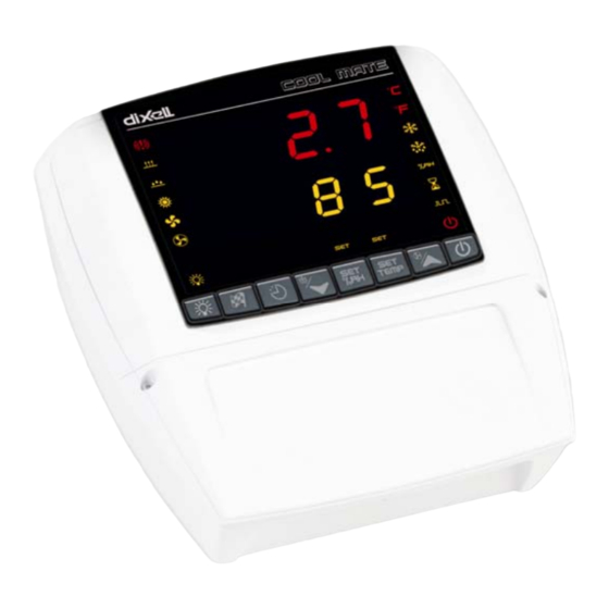
Switch ON and OFF the instrument. KEY COMBINATIONS To lock and unlock the keyboard To enter the programming mode. To exit the programming mode. 8.1 ICONS AND SYMBOLS Each LED function is described in the following table. XLH360 1592017410 XLH360 GB r1.0 15.04.2005.doc 6/16... - Page 7 Use o or n to input the security code in the flashing digit; confirm the figure by pressing “ SET %RH ”. The security code is “321“. If the security code is correct the access to “Pr2” is enabled by pressing “ SET %RH ” on the last digit. XLH360 1592017410 XLH360 GB r1.0 15.04.2005.doc 7/16...
-
Page 8: Parameter List
“End” message, the buzzer is turned on, and the regulation is stopped. trC=cL at the end of the stopping phase the controller gives the “End” message, the buzzer is turned on, and the regulation restarts from the running phase XLH360 1592017410 XLH360 GB r1.0 15.04.2005.doc 8/16... - Page 9 15) Number of activation of the pressure switch, during the “did” interval, before signalling the alarm event ÷ (I1F= PAL). If the nPS activation in the “did” time is reached, switch off and on the instrument to restart normal regulation. XLH360 1592017410 XLH360 GB r1.0 15.04.2005.doc 9/16...
-
Page 10: Digital Input
The compressor and the regulation are stopped. When the digital input is ON the compressor is always OFF. If the nPS activation in the did time is reached, switch off and on the instrument to restart normal regulation. XLH360 1592017410 XLH360 GB r1.0 15.04.2005.doc 10/16... -
Page 11: Installation And Mounting
The temperature range allowed for correct operation is 0 - 60 °C. Avoid places subject to strong vibrations, corrosive gases, excessive dirt or humidity. The same recommendations apply to probes. Let the air circulate by the cooling holes. Thanks to the case XLH360. See the following instructions for details. FIG. 2 FIG. - Page 12 Mount the frontal part using the previous 4 screws Fig. 1, D, E, F, G. (do not press excessively in order to avoid plastic deformation). After connecting the wires to the terminal blocks close the cover (Fig. 2, c) and fix it by the screws. XLH360 1592017410 XLH360 GB r1.0 15.04.2005.doc 12/16...
-
Page 13: Dimensions
Automatically the parameter list of the “Hot Key” is downloaded into the Controller memory, the “doL” message is blinking followed a by flashing “End”. After 10 seconds the instrument will restart working with the new parameters. Remove the “Hot Key”.. XLH360 1592017410 XLH360 GB r1.0 15.04.2005.doc 13/16... -
Page 14: Alarm Signalling
Storage temperature: -25÷60 °C. Relative humidity: 20 85% (no condensing) ÷ Measuring and regulation range: NTC probe: -40÷110°C (-58÷230°F) Resolution: 0,1 °C or 1°C or 1 °F (selectable). Accuracy (ambient temp. 25°C): ±0,5 °C ±1 digit XLH360 1592017410 XLH360 GB r1.0 15.04.2005.doc 14/16... -
Page 15: Xlh360 Wiring Connections
0.1°C o 1°F ÷ 25°C o 77°F Temperature alarm delay 0 ÷ 250 min Delay of temperature alarm at start-up 0.0 ÷ 23.5 h Alarm delay at the end of defrost 0 ÷ 250 min XLH360 1592017410 XLH360 GB r1.0 15.04.2005.doc 15/16... - Page 16 - - - Parameter table - - - - - - Software release - - - - - - Probes display Pb1÷Pb3 - - - Access to the protected parameter list - - - XLH360 1592017410 XLH360 GB r1.0 15.04.2005.doc 16/16...
Need help?
Do you have a question about the COOL MATE XLH360 and is the answer not in the manual?
Questions and answers