Advertisement
dIXEL
DIGITAL CONTROLLER
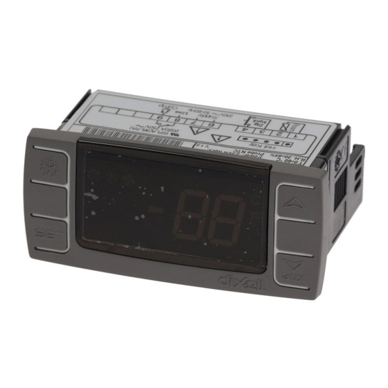
XR02CX
1. CONTENTS
1.
Contents __________________________________________________________________________ 1
2.
General warnings ___________________________________________________________________ 1
3.
General description __________________________________________________________________ 1
4.
Regulation_________________________________________________________________________ 1
5.
Defrost ___________________________________________________________________________ 1
6.
Front panel commands _______________________________________________________________ 1
7.
Parameters ________________________________________________________________________ 1
8.
Installation and mounting _____________________________________________________________ 2
9.
Electrical connections ________________________________________________________________ 2
10. How to use the hot key _______________________________________________________________ 2
11. Alarm signalling_____________________________________________________________________ 2
12. Technical data______________________________________________________________________ 2
13. Connections _______________________________________________________________________ 2
14. Default setting values ________________________________________________________________ 2
2. GENERAL WARNINGS
PLEASE READ BEFORE USING THIS MANUAL
•
This manual is part of the product and should be kept near the instrument for easy and quick
reference.
•
The instrument shall not be used for purposes different from those described hereunder. It cannot be
used as a safety device.
•
Check the application limits before proceeding.
SAFETY PRECAUTIONS
•
Check the supply voltage is correct before connecting the instrument.
•
Do not expose to water or moisture: use the controller only within the operating limits avoiding sudden
temperature changes with high atmospheric humidity to prevent formation of condensation
•
Warning: disconnect all electrical connections before any kind of maintenance.
•
Fit the probe where it is not accessible by the End User. The instrument must not be opened.
•
In case of failure or faulty operation send the instrument back to the distributor or to "Dixell S.p.A." (see
address) with a detailed description of the fault.
•
Consider the maximum current which can be applied to each relay (see Technical Data).
•
Ensure that the wires for probes, loads and the power supply are separated and far enough from each
other, without crossing or intertwining.
•
In case of applications in industrial environments, the use of mains filters (our mod. FT1) in parallel with
inductive loads could be useful.
3. GENERAL DESCRIPTION
Model XR02CX, format 32 x 74 x 50 mm, is a digital thermostat with off cycle defrost designed for
refrigeration applications at normal temperature. It provides a relay output to drive the compressor. It is also
provided with 2 NTC probe input. The instrument is fully configurable through special parameters that can be
easily programmed through the keyboard or the by HOTKEY.
4. REGULATION
THE REGULATION OUTPUT
The regulation is performed according to
the
temperature
measured
by
the
thermostat probe with a positive differential
from the set point: if the temperature
increases and reaches set point plus
differential the compressor is started and
then turned off when the temperature
reaches the set point value again.
In case of fault in the thermostat probe the start and stop of the compressor are timed through parameters
"Cy" and "Cn".
5. DEFROST
Defrost is performed through a simple stop of the compressor. Parameter "id" controls the interval
between defrost cycles, while its length is controlled by parameter "Md".
6. FRONT PANEL COMMANDS
KEYS COMBINATION
+
To lock or unlock the keyboard
+
To enter in programming mode
+
To return to room temperature display
LED
MODO
SIGNIFICATO
On
Compressore enabled
Flashing
Anti short cycle delay enabled (AC parameter)
XR02CX US.doc
Operating Manual
To display target set point, in
programming mode it selects a
parameter
or
confirm
an
operation
To start a manual defrost
In programming mode it browses
the parameter codes or increases
the displayed value
In programming mode it browses
the
parameter
codes
or
AUX
decreases the displayed value
XR02CX
On
Defrost in progress
Flashing
Dripping in progress
On
Measurement unit
Flashing
Programming mode
On
Measurement unit
Flashing
Programming mode
HOW TO SEE THE SET POINT
1.
Push and immediately release the SET key, the set point will be showed;
2.
Push and immediately release the SET key or wait about 5s to return to normal visualisation.
HOW TO CHANGE THE SETPOINT
1.
Push the SET key for more than 2 seconds to change the Set point value;
2.
The value of the set point will be displayed and the "°C" or "°F" LED starts blinking;
3.
To change the Set value push the o or n arrows within 10s.
4.
To memorise the new set point value push the SET key again or wait 10s.
HOW TO START A MANUAL DEFROST (ONLY XR02CX)
Push the DEF
key for more than 2 seconds and a manual defrost will start
HOW TO CHANGE A PARAMETER VALUE
To change the parameter's value operate as follows:
1. Enter the Programming mode by pressing the SET+
blinking).
2. Select the required parameter. Press the "SET" key to display its value
3. Use
or
to change its value.
4. Press "SET" to store the new value and move to the following parameter.
To exit: Press SET+
or wait 15s without pressing a key.
NOTE: the set value is stored even when the procedure is exited by waiting the time-out to expire.
HIDDEN MENU
The hidden menu includes all the parameters of the instrument.
HOW TO ENTER THE HIDDEN MENU
1. Enter the Programming mode by pressing the SET+
blinking).
2. Released the keys, then push again the SET+
displayed immediately followed from the Hy parameter.
NOW YOU ARE IN THE HIDDEN MENU.
3. Select the required parameter.
4. Press the "SET" key to display its value
5. Use
or
to change its value.
6. Press "SET" to store the new value and move to the following parameter.
To exit: Press SET+
or wait 15s without pressing a key.
NOTE1: if none parameter is present in L1, after 3s the "nP" message is displayed. Keep the keys
pushed till the L2 message is displayed.
NOTE2: the set value is stored even when the procedure is exited by waiting the time-out to expire.
HOW TO MOVE A PARAMETER FROM THE HIDDEN MENU TO THE FIRST
LEVEL AND VICEVERSA.
Each parameter present in the HIDDEN MENU can be removed or put into "THE FIRST LEVEL" (user
level) by pressing SET+
. In HIDDEN MENU when a parameter is present in First Level the decimal
point is on.
TO LOCK THE KEYBOARD
1.
Keep pressed for more than 3s the
and
2.
The "OF" message will be displayed and the keyboard will be locked. If a key is pressed more
than 3s the "OF" message will be displayed.
TO UNLOCK THE KEYBOARD
Keep pressed together for more than 3s the
and
7. PARAMETERS
REGULATION
Hy Differential: (0,1°C ÷ 25°C) Intervention differential for set point. Compressor Cut IN is SET
POINT + differential (Hy). Compressor Cut OUT is when the temperature reaches the set point.
LS Minimum SET POINT: (-55°C÷SET/-58°F÷SET): Sets the minimum value for the set point..
US Maximum SET POINT: (SET÷99°C/ SET÷99°F). Set the maximum value for set point.
ot
First probe calibration: (-9.9÷9.9°C) allows to adjust possible offset of the first probe.
P2 Evaporator probe presence: n= not present; y= the defrost stops by temperature.
oE Second probe calibration: (-9.9÷9.9°C) allows to adjust possible offset of the second probe
od Outputs activation delay at start up: (0÷99min) This function is enabled at the initial start up of
the instrument and inhibits any output activation for the period of time set in the parameter.
AC Anti-short cycle delay: (0÷50 min) minimum interval between the compressor stop and the
following restart.
Cy Compressor ON time with faulty probe: (0÷99 min) time during which the compressor is active
in case of faulty thermostat probe. With Cy=0 compressor is always OFF.
Cn Compressor OFF time with faulty probe: (0÷99 min) time during which the compressor is OFF
in case of faulty thermostat probe. With Cn=0 compressor is always active.
DISPLAY
CF Measurement unit: (°C÷°F) °C =Celsius; °F =Fahrenheit. WARNING: When the measurement
unit is changed the SET point and the values of the parameters Hy, LS, US, oE, o1, AU, AL
have to be checked and modified if necessary).
rE
Resolution (only for °C):(dE ÷ in) dE= decimal between -9.9 and 9.9°C; in= integer;
Ld
Default display: (P1 ÷ P2) P1= thermostat probe; P2= evaporator probe. SP=Set point
dy
Display delay: (0÷15 min.) when the temperature increases, the display is updated of 1 °C/1°F
after this time.
DEFROST
dE Defrost termination temperature: (-50÷50°C) if ot=Y it sets the temperature measured by the
evaporator probe, which causes the end of defrost.
1598024510
keys for 3s ("°C" or "°F" LED starts
keys for 3s ("°C" or "°F" LED starts
keys for more than 7s. The L2 label will be
keys.
keys till the "on" message will be displayed.
1/2
Advertisement

Related Manuals for dixell XR02CX


Summary of Contents for dixell XR02CX
-
Page 1: Parameters
L2 message is displayed. Model XR02CX, format 32 x 74 x 50 mm, is a digital thermostat with off cycle defrost designed for NOTE2: the set value is stored even when the procedure is exited by waiting the time-out to expire. -
Page 2: Installation And Mounting
Software release 8. INSTALLATION AND MOUNTING NOTE: Fast-on maximum current 16A Instrument XR02CX shall be mounted on vertical panel, in a 29x71 mm hole, and fixed using the special bracket supplied. 14. DEFAULT SETTING VALUES The temperature range allowed for correct operation is 0÷60 °C.
Need help?
Do you have a question about the XR02CX and is the answer not in the manual?
Questions and answers
Can you use blue tooth with this? XRO2CX-4N1F1
The provided information does not mention Bluetooth connectivity for the Dixell XR02CX.
This answer is automatically generated