
Related Manuals for Miller ST 44 Series


Summary of Contents for Miller ST 44 Series
- Page 1 OM-216 655N 2013−07 Processes MIG (GMAW) Welding Flux Cored (FCAW) Welding Description Wire Feeder ST 44 Series Wire Feeder OWNER’S MANUAL www.MillerWelds.com...
- Page 2 From Miller to You Thank you and congratulations on choosing Miller. Now you can get the job done and get it done right. We know you don’t have time to do it any other way. That’s why when Niels Miller first started building arc welders in 1929, he made sure his products offered long-lasting value and superior quality.
-
Page 3: Table Of Contents
..............5-1. ST 44 Series Panel Controls . -
Page 4: Declaration Of Conformity
DECLARATION OF CONFORMITY for European Community (CE marked) products. ITW Welding Products Italy S.r.l Via Privata Iseo 6/E, 20098 San Giuliano M.se, (MI) Italy declares that the product(s) identified in this declaration conform to the essential requirements and provisions of the stated Council Directive(s) and Standard(s). -
Page 5: Section 1 − Safety Precautions - Read Before Using
SECTION 1 − SAFETY PRECAUTIONS - READ BEFORE USING som 2011−10 Protect yourself and others from injury — read, follow, and save these important safety precautions and operating instructions. 1-1. Symbol Usage DANGER! − Indicates a hazardous situation which, if Indicates special instructions. - Page 6 D Remove stick electrode from holder or cut off welding wire at FUMES AND GASES can be hazardous. contact tip when not in use. D Wear oil-free protective garments such as leather gloves, heavy Welding produces fumes and gases. Breathing shirt, cuffless trousers, high shoes, and a cap.
-
Page 7: Additional Symbols For Installation, Operation, And Maintenance
1-3. Additional Symbols For Installation, Operation, And Maintenance FIRE OR EXPLOSION hazard. BATTERY EXPLOSION can injure. D Do not install or place unit on, over, or near D Do not use welder to charge batteries or jump combustible surfaces. start vehicles unless it has a battery charging D Do not install unit near flammables. -
Page 8: California Proposition 65 Warnings
1-4. California Proposition 65 Warnings Welding or cutting equipment produces fumes or gases This product contains chemicals, including lead, known to which contain chemicals known to the State of California to the state of California to cause cancer, birth defects, or other cause birth defects and, in some cases, cancer. -
Page 9: Section 2 − Definitions
SECTION 2 − DEFINITIONS 2-1. Additional Safety Symbols And Definitions Some symbols are found only on CE products. Warning! Watch Out! There are possible hazards as shown by the symbols. Safe1 2012−05 Wear dry insulating gloves. Do not touch electrode (wire) with bare hand. Do not wear wet or damaged gloves. Safe57 2012−05 Disconnect input plug or power before working on machine. -
Page 10: Miscellaneous Symbols And Definitions
Use ventilating fan to remove fumes. Safe61 2012−06 Keep flammables away from welding. Do not weld near flammables. Safe62 2012−06 Welding sparks can cause fires. Have a fire extinguisher nearby, and have a watchperson ready to use it. Safe63 2012−06 Do not weld on drums or any closed containers. -
Page 11: Section 3 − Specifications
SECTION 3 − SPECIFICATIONS 3-1. Serial Number And Rating Label Location The serial number and rating information for this product is located on back . Use rating label to determine input power requirements and/or rated output. For future reference, write serial number in space provided on back cover of this manual. 3-2. -
Page 12: Section 4 − Installation
SECTION 4 − INSTALLATION 4-1. Equipment Connection Diagrams CV Welding Power Source with 14 pin Amphenol Receptacle Interconnecting Control Cord (Required) Weld Cable (Required) Work 4-2. 14-Pin Plug Information Pin* Pin Information 24 volts AC with respect to pin G. Contact closure to A completes 24 volts AC contactor control circuit. -
Page 13: Installing Wire Guide And Drive Roll
4-4. Installing Wire Guide And Drive Roll Inlet Wire Guide Intermediate Wire Guide Install and secure inlet wire guide, and intermediate wire guide. Drive Roll (4) Install drive rolls and turn drive roll 1−2 nut one click. During maintenance intervals, remove drive rolls, and clean grooves using a wire brush. -
Page 14: Section 5 − Operation
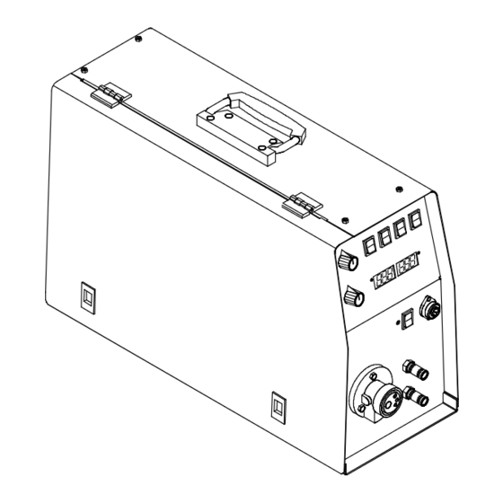
SECTION 5 − OPERATION 5-1. ST 44 Series Panel Controls Voltage Control Purge Control 2T−4T Switch Power ON-OFF Digital Voltmeter/MPM Remote Control Receptacle In-Out Cooling Connections For Torch Torch Connection 10 Panel/Remote Control Switch 11 Wire Speed Control 12 Circuit Breaker... -
Page 15: Section 6 − Maintenance & Troubleshooting
SECTION 6 − MAINTENANCE & TROUBLESHOOTING 6-1. Routine Maintenance Disconnect power before maintaining. 3 Months Repair Or Clean And Replace Replace Tighten Unreadable Cracked Weld Labels Weld Cable Terminals Replace Cracked Parts 14-Pin Cord Gun Cable Gas Hose 6 Months Blow Out Or Vacuum Inside, Clean Drive Rolls During Heavy Service, Clean... -
Page 16: Troubleshooting
6-2. Troubleshooting Problem Solution Unit is completely inoperative. Check continuity of Power switch S1, and replace if necessary. Reset circuit breaker CB1 if open. Check input power source. See welding power source Technical Manual. Wire does not feed, unit completely inop- Turn Power switch On. -
Page 17: Section 6 − Electrical Diagram
SECTION 7 − ELECTRICAL DIAGRAM 956.142.484-C OM-216 655 Page 13... -
Page 18: Section 7 − Parts List
SECTION 8 − PARTS LIST Hardware is common and not available unless listed. Fig. 8-2 956.142.672_C Figure 8-1. ST 44 Complete Assembly (Optional Equipment Shown) Item Dia. Part Description Mkgs. Basic Digital Figure 8−1. ST 44 Complete Assembly .. - Page 19 Item Dia. Part Description Mkgs. Basic Digital Figure 8−1. ST 44 Complete Assembly ....556049403 Fitting, Quick Connect Water, Male Red ......
- Page 20 Hardware is common and not available unless listed. 956.142.674_B Figure 8-2. 4 Roll Wire Drive Assembly (All Models) OM-216 655 Page 16...
- Page 21 Item Dia. Part Description Mkgs. Figure 8-2. 4 Roll Wire Drive Assembly (All Models) ..057010051 . . . Motor, Gear 24 V 100W ..........
- Page 22 Table 8-1. Drive Roll And Wire Guide Kits (4 Drive Roll) Base selection of drive rolls upon the following recommended usages: 1. V-Grooved rolls for hard wire. 2. U-Grooved rolls for soft and soft shelled cored wires. 3. U-Cogged rolls for extremely soft shelled wires (usually hard surfacing types). 4.
- Page 23 Effective January 1, 2013 (Equipment with a serial number preface of MD or newer) This limited warranty supersedes all previous Miller warranties and is exclusive with no other guarantees or warranties expressed or implied. LIMITED WARRANTY − Subject to the terms and conditions 90 Days —...
- Page 24 File a claim for loss or damage during Phone: 39 (0) 2982901 Fax: 39 (0) 298290-203 shipment. email: miller@itw−welding.it For assistance in filing or settling claims, contact your distributor and/or equipment manufacturer’s Transportation Department. © ORIGINAL INSTRUCTIONS − PRINTED IN USA 2013 Miller Electric Mfg. Co. 2013−01...
Need help?
Do you have a question about the ST 44 Series and is the answer not in the manual?
Questions and answers
24V positive, should it be connected to A and B?
No, the 24V positive should be connected to pin A, while pin B is used for contact closure to A, completing the 24V AC contactor control circuit.
This answer is automatically generated
I just connected the 24V positive to A and the common to G. Do I need to do anything else to get the device to start?
After connecting the 24V positive to A and the common to G, the following additional steps are needed to start the Miller ST 44 Series device:
1. Complete the Contactor Control Circuit – Ensure that contact closure between A and B is established to complete the 24V AC contactor control circuit.
2. Power On the Device – Use the power ON-OFF switch to turn on the device.
3. Set Controls as Needed – Adjust voltage control, wire speed control, and other relevant settings according to the welding requirements.
4. Ensure Proper Connections – Confirm that the torch, gas, and weld cables are securely connected.
5. Check Circuit Breaker – Verify that the circuit breaker is not tripped before operation.
These steps ensure the device is properly started and ready for welding.
This answer is automatically generated
Thanks, by pressing the trigger, the wire comes out and the gas relay works, but it is not welded. What do you think is the problem?
If the Miller ST 44 Series is feeding wire and activating the gas relay but not welding, possible causes include:
1. Poor Work Clamp Connection – Ensure the work clamp is properly connected to the workpiece to complete the circuit.
2. Faulty Power Source or Welding Cable – Check the welding power source and cables for damage or loose connections.
3. Defective Gun or Trigger Leads – Inspect the gun trigger leads for continuity and repair or replace if necessary.
4. Incorrect Machine Settings – Verify voltage and wire feed speed settings to ensure proper operation.
Checking these components should help identify and resolve the issue.
This answer is automatically generated
Mr. Anderson, thank you for your response I procured and installed a 24V power supply Now the device is on and all its components are working, but it does not spark when you press the trigger, what is the problem?
If the Miller ST 44 Series device is powered on but does not spark when the trigger is pressed, possible issues include:
1. Trigger Switch Issue – Check the gun trigger for proper operation. Refer to the gun Owner’s Manual.
2. Jog Button Problem – Check the continuity of Jog button S3 and replace if necessary.
3. Motor Control Board Issue – Inspect the motor control board PC1 and its connections, and replace if necessary.
4. Trigger Leads Short – Check for a short between the gun trigger leads and the weld cable, then repair or replace the gun trigger leads if needed.
These steps should help diagnose and resolve the issue.
This answer is automatically generated
How to start the device with out power supply I lose the power supply
The Miller ST 44 Series device requires input power to operate. There is no information in the provided context on how to start the device without a power supply.
This answer is automatically generated
I don't have the information of the device that pin 14 connects to to complete the B pin path so that's why
Can you tell me what to connect to B and other bases?
This photo of the power supply that we prepared and connected to the device