Table of Contents
Advertisement
Please read this manual prior of using the air dryer. Keep the manual readily available for
reference.
Operation Manual
PRODUCT NAME
Refrigerated Air Dryer
MODEL / Series
IDFB3E-11
IDFB4E-11
IDFB6E-11
IDFB8E-11
IDFB11E-11
IDFB15E-11
Initial issue April, 2005
5th edition January, 2011
-A
-A,R,T,V
-A,K,R,T,V
-A,K,R,T,V
-A,K,R,T,V
-K,R,T,V
© 2011 SMC CORPORATION All Rights Reserved.
IDX-OM-J001-E
Advertisement
Table of Contents

Related Manuals for SMC Networks IDFB3E-11


Summary of Contents for SMC Networks IDFB3E-11
- Page 1 IDX-OM-J001-E Initial issue April, 2005 5th edition January, 2011 Operation Manual PRODUCT NAME Refrigerated Air Dryer MODEL / Series IDFB3E-11 IDFB4E-11 -A,R,T,V IDFB6E-11 -A,K,R,T,V IDFB8E-11 -A,K,R,T,V IDFB11E-11 -A,K,R,T,V IDFB15E-11 -K,R,T,V Please read this manual prior of using the air dryer. Keep the manual readily available for reference.
- Page 2 Dear Customers Thank you for selecting SMC Refrigerated Air Dryer. This operation manual must be read and understood thoroughly before using the equipment. It provides all essential information pertaining to safety, as well as, maximizing equipment efficiency in order to extend the life of the equipment.
-
Page 3: Table Of Contents
Table of Contents Table of Contents To Customers Chapter i Safety Instructions i - 1 Warning: Before Using Air Dryer ............i - 1 i - 1 - 1 Hazard, Warning, and Caution Used in This Manual ........i - 1 i - 2 Danger Classifications/Position of Hazard warning Label ..i - 2 i - 2 - 1... - Page 4 Table of Contents Chapter 7 Specification for Option A 7 - 1 Safety instructions ..................7 - 1 7 - 2 Specification ....................7 - 1 7 - 3 Air piping ...................... 7 - 1 7 - 4 Dryer specifications .................
-
Page 5: Chapter I Safety Instructions
i Safety Instructions Safety Instructions Be sure to read and comprehend important cautionary notifications in this operation manual before use Do not operate the equipment without the cover panel. Warning: Before Using Air Dryer In this chapter, the stated contents are especially about safety. This Air Dryer is installed downstream of the air compressor to remove moisture. -
Page 6: Danger Classifications/Position Of Hazard Warning Label
i Safety Instructions Danger Classifications & Position of Hazard warning Labels To help you recognize the hazards, the unit utilizes special graphics to indicate different hazards. Confirm the contents of the hazards and the location of the labels before operation. Warning Only properly trained, qualified personnel are allowed to perform tasks such as: •... -
Page 7: Hazard Of Electricity
i Safety Instructions i-2-2 Hazard of Electricity Warning Inside of this equipment, there is a power-supplying section with high voltage separated by the cover panel. Do not operate the equipment with the cover panel off. i-2-3 Hazard of Hot Surface Warning Since this equipment has parts that become hot during operation, there is the danger of burn-associated injuries. - Page 8 i Safety Instructions i-2-6 Positions of Danger Warning Label Warning Read with caution and pay attention to the notations of danger warning labels. Do not remove or rub danger warning labels. Confirm the positions of danger warning labels. WARNING 警告 1 Remove panels for maintenance only.
-
Page 9: Hazard Of Refrigerant
i Safety Instructions i-2-7 Hazard of Refrigerant Caution This equipment uses Fluorocarbon (HFC) as a refrigerant. It is strictly forbidden to emit Fluorocarbon into the atmosphere. Before you repair the refrigerant circuit, you should collect the refrigerant with proper evacuation system. The collected refrigerant should be properly recycled by qualified agency. -
Page 10: I-2-8 Cautions About Usage
i Safety Instructions i-2-8 Cautions about Usage Warning Please follow the instructions on all warning labels. Do not remove or deface warning labels, and confirm the location of warning labels. CAUTION 注 意 1 Read manual before operation. 2 Ensure vantilation and maintenance space. -
Page 11: I-3 Disposal
i Safety Instructions Disposal When you dispose of the equipment, you should collect the refrigerant and the refrigerant oil inside the refrigerant circuit. Caution This equipment contains Fluorocarbon HFC. It is strictly forbidden to emit Fluorocarbon into the atmosphere. Before you repair the refrigerant circuit, you should collect the refrigerant with proper evacuation system. -
Page 12: Chapter 1 Parts Name And Functions
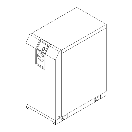
1 Name and Functions Parts Parts Name and Functions Parts Name and Functions • IDFB3E Top Ventilation Grille Switch with Lamp (Outlet) (ON/OFF Switch) Hot air will be exhausted The lamp is continuously ON from condenser by fan. No during normal operation. Use it obstacles shall be allowed for ON/OFF operations. - Page 13 1 Name and Functions Parts • IDFB3E Electrical Terminal Cover You can see the terminal block when you remove this cover. Connect the power cable through the membrane Front grommet. L N PE Customer Connection Side Membrane Grommet Power cord outlet 1 - 2...
- Page 14 1 Name and Functions Parts • IDFB4E to 15E Switch with Lamp Ventilation Grille The lamp is continuously ON Hot air will be exhausted by during normal operation. condenser fan. Do not block these vents. Evaporation Thermometer Indicates the evaporating temperature of refrigerant on low-pressure side.
- Page 15 1 Name and Functions Parts • IDFB4E to 11E Rear Panel You can see the terminal block when you remove this cover. Connect the power cable through the membrane grommet Front L N PE Customer Connection Side Membrane Grommet Power cord inlet •...
-
Page 16: Transportation
2 Transportation / Installation Transportation/Installation Warning Only properly trained, qualified personnel are allowed to perform tasks such as: • Operation, installation, relocation of equipment and maintenance works. Strongly recommend to prepare the spare dryer when applying the dryer for • important equipment or system. -
Page 17: Installation
2 Transportation / Installation 2-2 Installation 2-2-1 Location The equipment should not be used or stored in the following conditions: Those conditions will cause not only malfunction but also failures. Environment where the equipment is exposed Circumstances where not enough clearance •... -
Page 18: Air Piping
2 Transportation / Installation 2-2-2 Anchorage The air dryer should be installed on a vibration-free, stable, horizontal, flat surface. • Refer to “Chapter6 6-2 Dimensions” for the dimensions. • • IDFB3E to 15E should be bolted by anchor bolts to prevent falling. We recommend the anchor bolt sets that we are selling separately as accessories. -
Page 19: Electric Wiring
2 Transportation / Installation Warning To handle drain discharge, follow the safety guidelines such as wearing protective goggles, apron, and gloves. In case that oil gets mixed in the wastewater discharged from the auto drain, the liquid would be considered as toxic waste and treatment is necessary in accordance with local regulations. Electric Wiring 2-2-5 Warning... - Page 20 2 Transportation / Installation Length of the power cable The maximum length of the power cable should be no more than 98feet (30m). Connecting to the power supply Connect the power cable and the ground to the terminal block Wiring procedure 1.Remove the terminal block cover or the rear panel.
- Page 21 2 Transportation / Installation 2-3 Cautions for Reinstallation Caution Only properly trained, qualified personnel are allowed to perform reinstallation. If the equipment is moved and reinstalled in another place after some trial operations, the following instructions must be followed as well as procedures in Chapter 2. Removing the power cable Disconnect the power source before removing the power cable.
-
Page 22: Check Points Before Operation
3 Operation / Shutdown Operation/Shutdown Caution Only properly trained and qualified personnel are allowed to perform operation/shutdown of the equipment. Check points before operation Before trial run, check the following points: Installed Conditions: • By visual inspection , check that the equipment is level. Model IDFB3E to 15E, make sure the equipment is tied down with anchor bolts. -
Page 23: Shutdown
3 Operation / Shutdown Shutdown Turn off the ON/OFF switch. • The lamp will go out and then, the operation will stop. Depending on the condition of operation, hot • air continues to be emitted from the ventilation grille by the cooling fan for a while after turning off the switch. -
Page 24: Daily Inspection
4 Maintenance Maintenance 4-1 Daily Inspection Check following points during normal operations. If you find some problems, immediately stop the dryer and refer to “Chapter 5 Troubleshooting” as soon as possible. There is no air leaks. • The running lamp is on during operation •... - Page 25 4 Maintenance Danger Since this equipment has parts that become hot during operation, there is the danger of burn-associated injuries. These parts remain hot even after power is off. Wait until the unit has cooled down before touching. Danger There is the risk of touching discharged drain fluid during replacement. Wear protective goggles, aprons, and gloves to prevent direct contact.
- Page 26 4 Maintenance Grip the case assembly lightly and Mark pull down the lock botton with thumb. Then, directly turn the case assembly left (or right) to match the marks. Remove thumb from the lock button and pull the Lock Button case assembly down slowly (vertically) to remove the case assembly.
-
Page 27: Chapter 5 Troubleshooting
5 Troubleshooting Troubleshooting Should any problem occur, inspect the following table, and if the problem cannot be solved, shut off the power supply and then contact one of our sales offices for further instructions. Problem Probable Causes Remedy Air dryer does not Perform proper connection on the power cord and Power cord or plug is loose or operate and run... -
Page 28: Specifications
6 References References Specifications Model IDFB3E IDFB4E IDFB6E IDFB8E IDFB11E IDFB15E Specification At Expected Outlet 10 SCFM 15 SCFM 25 SCFM 41 SCFM 59 SCFM 71 SCFM Press.Dew Point of 37° F (17 m (25 m (43 m (70 m (100 m (120 m (2.8°C) -
Page 29: Dimensions
Note 3: When short period power shortage (including instantly recovered shortage) is recovered, it may take a longer starting period than usual starting or may not start due to the protective devices. Dimensions IDFB3E-11 Table1. Thread symbol UNIT : inch (mm) SYMBOL... - Page 30 6 References IDFB15E-11 Table1. Thread symbol SYMBOL DRAIN TUBE SIZE NONE 10mm UNIT : inch (mm) Dimensions (inch [mm]) Thread Model Size 16.1 18.6 12.0 13.0 IDFB3E [226] [410] [473] [67] [125] [304] [33] [73] [31] [36] [154] [21] [330] [231] [15] 17.8...
-
Page 31: Electrical Circuit
6 References 6-3 Electrical Circuit IDFB3E Power Cable SYMBOL DESCRIPTION Compressor Motor Terminal Block for Option Fan Motor Overload Relay (Inside of compressor terminal cover) PTC Starter Switch with Lamp Pressure Switch Terminal Block IDFB4E / 6E / 8E GFCI For Otion R Power Cable Terminal Block for Option... - Page 32 6 References GFCI IDFB11E For Otion R ※1 ※2 Terminal Block for Option S Power Cable SYMBOL DESCRIPTION Compressor Motor FM1~2 Fan Motor Overload Relay (Inside of compressor terminal cover) PTC Starter Switch with Lamp For Otion V Pressure Switch Terminal Block Magnetic Contactor GFCI...
- Page 33 6 References Compressed Air and Refrigerant Circuit/Operation Principles BASIC MODEL IDFB3E-11 Drain Separator Air Inlet Air Outlet Reheter Cooler Drain Outlet Capillary Tube Capacity Control Valve Condensor Pressure Switch Evaporation Fan M otor Com pressor Thernareter IDFB4E to 15E-11 A ir In le t...
-
Page 34: Service Parts List
6 References IDFB4E to 11E-11-A H e a t E x c h a n g e r A ir In le t A ir O u tle t E v a p o ra tio n T h e rm o m e te r C a p a c ity D ra in S e p a ra to r C o n tro l V a lv e... -
Page 35: Safety Instructions
7 Specification for Option A Specification for Option A Safety instructions When handling the product, take care to the following precautions. Warning Shut off the power supply when removing the panel for maintenance work, etc. The product has a fan(s) and could cause serious danger to operators. Specification The specification for this air dryer is used for cooling down the compressed air. -
Page 36: Safety Instructions
9 Specification for Option K Specification for Option K This product mounts the auto drain in Item 2 Specifications. When performing the installation and maintenance of the product, the following points must be understood and followed. Additionally, for replacement work, read 4-2 “Periodical Maintenance” of the Operation Manual of standard product and keep safety. -
Page 37: Specifications
9 Specification for Option K Specifications The auto drain has a maximum operating pressure of 240psig (1.6MPa) and uses the metal case with a fluid level indicator. IDFB6E to 15E AD48N-8Z-X2110(Thread Symbol “N”) AD48-8-X2110(Thread Symbol “None”) Level gauge Heat insulator KQ2H11-35S(Thread Symbol “N”) KQ2H10-02S(Thread Symbol “None”) Drain Port... -
Page 38: Safety Instructions
9 Specification for Option R Specification for Option R This product mounts the Ground Fault Circuit Interrupter (GFCI) in Item 2. It will shut off the power supply in case the product should have over current or current leakage. Additionally, the power supply should be connected directly to the primary side of the GFCI. -
Page 39: Specifications Of Gfci
9 Specification for Option R Specifications of the GFCI Dryer model number Specifications of GFCI IDFB4E to 15E-11 -R Rated current: 15A, Current sensitivity: 30mA How to connect the power supply Connect the power cables in the following procedure. 1) Take off the rear panel. 2) Insert the power cable prepared by the customer into the power code fixture and bring the power cable near the terminal base through the base hole. - Page 40 9 Specification for Option R IDFB15E Connect to power code Connector width 0.37inch (9.5mm) or less Rear panel L N GFCI Connect to earth code Electrical Connector width 0.25inch (6.5mm) or less entry 9 - 3...
-
Page 41: Safety Instructions
10 Specification for Option T Specification for Option T This product mounts the terminal block which can transfer the operation and failure signals to Item 2 Specifications. The signals are a no voltage contact style. For details, refer to Item 2 or later. 10-1 Safety instructions When handling the product, take care to the following precautions. -
Page 42: Remote Operation
10 Specification for Option T Remote operation 10-3 For the remote operation, turn on and off the power supply side under the condition of the illuminated switch ON. Keep 3 min. at minimum after stopping the product to restart even for the remote operation. If the product is restarted within less than 3 min., protective equipment (overload relay) may activate and prevent the product from restarting. -
Page 43: Electric Circuit
10 Specification for Option T IDFB15E Rear panel Terminal block L N 1 2 Connections for customer Connecter width: 0.25inch (6.5mm) or less Suitable wire Power cord: 0.002inch (1.25mm ) to 0.003inch (2mm Signal cord: 0.0008inch (0.5 mm ) to 0.003inch (2mm... - Page 44 10 Specification for Option T IDFB15E-11 -T GFCI For Option R Operation Failure SYMBOL DESCRIPTION Compressor Motor FM1~5 Fan Motor Overload Relay For Otion V Pressure Switch Switch with Lamp PTC Starter Magnetic Contactor Time Delay Relay Terminal Block Capacitor For Compressor Motor Stating Relay GFCI Ground Fault Circuit Interrupter...
-
Page 45: Chapter 11 Specification For Option
11 Specification for Option V Specification for Option V This product mounts the timer operated auto drain in Item 2 Specifications. When performing the installation and maintenance work for the product, the following points must be understood and followed. Additionally, read Item 3 for replacement work. 11-1 Safety instructions When handling the product, take care to the following precautions. -
Page 46: How To Perform Maintenance
11 Specification for Option V IDF-S0199 (AC115V) KQ2L11-04S (Thread Symbol"N") KQ2L10-04S (Thread Symbol"None") 3/8 (Thread Symbol"N") φ10 (Thread Symbol"None") Power supply voltage of dryer AC115V Order number (service parts) IDF-S0199 Max. operating pressure 240psig (1.6MPa) Fluid Drain Power supply voltage of drain timer AC115V±10% (60Hz) ON time 0.5sec... -
Page 47: Service Record
12 Service Record Service Record 12-1 Service Record It is recommended to keep a maintenance/service record. Parts No. Description Maintenance/Service Work Description Date 12 - 1...
Need help?
Do you have a question about the IDFB3E-11 and is the answer not in the manual?
Questions and answers