Table of Contents
Advertisement
Quick Links
Refrigerated Air Dryer
Please read this manual prior of using the air dryer.
Keep the manual readily available for reference.
Operation Manual
PRODUCT NAME
MODEL / Series
IDU3E-23-C,K,L,R,T,V
IDU4E-23-C,K,L,R,T,V
IDU6E-23-C,K,L,R,T,V
Initial issue: October, 2006
3nd edition: November, 2016
© 2016 SMC CORPORATION All Rights Reserved.
IDX-OM-K037-C
Advertisement
Table of Contents

Related Manuals for SMC Networks IDU3E-23-C


Summary of Contents for SMC Networks IDU3E-23-C
- Page 1 3nd edition: November, 2016 Operation Manual PRODUCT NAME Refrigerated Air Dryer MODEL / Series IDU3E-23-C,K,L,R,T,V IDU4E-23-C,K,L,R,T,V IDU6E-23-C,K,L,R,T,V Please read this manual prior of using the air dryer. Keep the manual readily available for reference. © 2016 SMC CORPORATION All Rights Reserved.
- Page 2 Dear Customers Thank you for selecting SMC Refrigerated Air Dryer. This operation manual must be read and understood thoroughly before using the product. It provides all essential information pertaining to safety, as well as, maximizing product efficiency in order to extend the life of the product. In addition, it is strongly recommended that you follow all the safety guidelines and regulations set forth by the local government agency for proper installation and usage.
-
Page 3: Table Of Contents
Table of Contents Table of Contents To Customers Chapter i Safety Instructions i - 1 Warning: Before Using Air Dryer ............i - 1 i - 1 - 1 Hazard, Warning, and Caution Used in This Manual ........i - 1 i - 2 Danger Classifications/Position of Hazard warning Label .. - Page 4 Table of Contents Chapter 6 References ................... 6 – 1 6 - 1 Specifications 6 - 2 Refrigerant with GWP reference ............6 - 1 6 - 3 Dimensions ....................6 - 2 6 - 4 Electrical Circuit ..................6 - 2 6 - 5 Compressed Air and Refrigerant Circuit / Operation Principles ..
-
Page 5: Chapter I Safety Instructions
i Safety Instructions Safety Instructions Be sure to read and comprehend important cautionary notifications in this operation manual before use Do not operate the product without the cover panel. Warning: Before Using Air Dryer In this chapter, the stated contents are especially about safety. This Air Dryer is installed downstream of the air compressor to remove moisture. -
Page 6: Danger Classifications/Position Of Hazard Warning Label
i Safety Instructions Danger Classifications & Position of Hazard warning Labels To help you recognize the hazards, the unit utilizes special graphics to indicate different hazards. Confirm the contents of the hazards and the location of the labels before operation. Warning ... -
Page 7: Hazard Of Electricity
i Safety Instructions Hazard of Electricity i-2-2 Warning Inside of this product, there is a power-supplying section with high voltage separated by the cover panel. Do not operate the product with the cover panel off. Hazard of Hot Surface i-2-3 Warning Since this product has parts that become hot during operation, there is the danger of burn-associated injuries. - Page 8 i Safety Instructions Positions of Danger Warning Label i-2-6 Warning Read with caution and pay attention to the notations of danger warning labels. Do not remove or rub danger warning labels. Confirm the positions of danger warning labels. WARNING 警告 1 Remove panels for maintenance only.
-
Page 9: I-2-7 Hazard Of Refrigerant
i Safety Instructions Hazard of Refrigerant i-2-7 Caution This product uses Fluorocarbon (HFC) as a refrigerant. It is strictly forbidden to emit Fluorocarbon into the atmosphere. Before you repair the refrigerant circuit, you should collect the refrigerant with proper evacuation system. The collected refrigerant should be properly recycled by qualified agency. -
Page 10: I-2-8 Cautions About Usage
i Safety Instructions Cautions about Usage i-2-8 Warning Please follow the instructions on all warning labels. Do not remove or deface warning labels, and confirm the location of warning labels. CAUTION 注意 1 Read manual before operation. 2 Ensure vantilation and maintenance space. -
Page 11: I-3 Disposal
i Safety Instructions Disposal When you dispose of the product, you should collect the refrigerant and the refrigerant oil inside the refrigerant circuit. Caution This product contains Fluorocarbon HFC. It is strictly forbidden to emit Fluorocarbon into the atmosphere. Before you repair the refrigerant circuit, you should collect the refrigerant with proper evacuation system. -
Page 12: I - 4 Limited Warranty And Disclaimer / Compliance Requirements
i Safety Instructions i – 4 Limited warranty and Disclaimer / Compliance Requirements The product used subject to the following “Limited warranty and Disclaimer“ and “Compliance Requirements. Read and accept them before using the product. Limited warranty and Disclaimer The warranty period of the product is 1 year in service or 1.5 years after the product is delivered. Also, the product may have specified durability, running distance or replacement parts. -
Page 13: Chapter 1 Parts Name And Functions
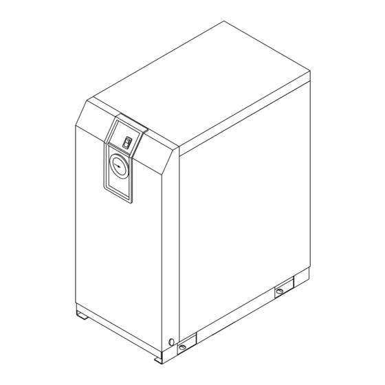
1 Name and Functions Parts Parts Name and Functions Parts Name and Functions • IDU3E to 6E Switch with Lamp Ventilation Grille The lamp is continuously ON Hot air will be exhausted by during normal operation. condenser fan. Do not block these vents. - Page 14 1 Name and Functions Parts • IDU3E to 6E Rear Panel You can see the terminal block when you remove this cover. Connect the power cable through the membrane grommet Front ( ) N PE Customer Connection Side Terminal Connecting Screw: M3 Ring terminals: 1.25-3 (Width 6.5mm and below) (Screw head dimension: 0.25”...
-
Page 15: Transportation
2 Transportation / Installation Transportation / Installation Warning Only properly trained, qualified personnel are allowed to perform tasks such as: Operation, installation, relocation of product and maintenance works. Strongly recommend to prepare the spare dryer when applying the dryer for important product or system. -
Page 16: Installation
2 Transportation / Installation Installation 2 - 2 Location 2-2-1 The product should not be used or stored in the following conditions: Those conditions will cause not only malfunction but also failures. Environment where the product is exposed to Locations where danger of thunder is apparent. -
Page 17: Anchorage
2 Transportation / Installation Anchorage 2-2-2 The air dryer should be installed on a vibration-free, stable, horizontal, flat surface. Refer to “Chapter6 6-2 Dimensions” for the dimensions. IDU3E~6E should be bolted by anchor bolts to prevent falling. We recommend the anchor bolt sets that we are selling separately as accessories. -
Page 18: Electric Wiring
2 Transportation / Installation Warning To handle drain discharge, follow the safety guidelines such as wearing protective goggles, apron, and gloves. In case that oil gets mixed in the wastewater discharged from the auto drain, the liquid would be considered as toxic waste and treatment is necessary in accordance with local regulations. Electric Wiring 2-2-5 Warning... - Page 19 2 Transportation / Installation Wiring procedure Remove the terminal block cover or the rear panel. Insert the cord through the rubber grommet and connect it to the terminal block (refer to the label on the terminal block). M3 screw tightening torque: 0.6 to 1Nm ...
-
Page 20: Check Points Before Operation
3 Operation / Shutdown Operation / Shutdown Caution Only properly trained and qualified personnel are allowed to perform operation/shutdown of the product. Check points before operation Before trial run, check the following points: Installed Conditions: By visual inspection , check that the product is level. Model IDU3E to 6E, make sure the product is tied down with anchor bolts. -
Page 21: Shutdown
3 Operation / Shutdown Shutdown Turn off the ON/OFF switch. The lamp will go out and then, the operation will stop. Depending on the condition of operation, hot air continues to be emitted from the ventilation grille by the cooling fan for a while after turning off the switch. -
Page 22: Daily Inspection
4 Maintenance Maintenance Daily Inspection 4 - 1 Check following points during normal operations. If you find some problems, immediately stop the dryer and refer to “Chapter 5 Troubleshooting” as soon as possible. There is no air leaks. The running lamp is on during operation ... - Page 23 4 Maintenance Warning ・ Maintenance of the air dryer should only be carried out by someone with sufficient knowledge and experience of air dryers and related equipment. ・ Before carrying out maintenance, the important warnings in this manual must be thoroughly read and understood.
- Page 24 4 Maintenance Lock button ・ Open the residual pressure release cock at the drain tube connection port to release air and drain fluid left in the product. Residual (Leave the drain tube connected and hold it with pressure hand so that it does not get twisted.) rerease cock ・...
-
Page 25: Chapter 5 Troubleshooting
5 Troubleshooting Troubleshooting Should any problem occur, inspect with the following table, and if the problem cannot be solved, shut off the power supply and then contact one of our sales offices for further instructions. Problem Probable Causes Remedy Air dryer does not Perform proper connection on the power cord and Power cord or plug is loose or operate and run... -
Page 26: 6-1 Specifications
6 References References 6-1 Specifications Model IDU3E IDU4E IDU6E Specification At Outlet Air Flow Rate 0.32m /min 0.52m /min 0.75m /min Pressure (ANR)(Note 1) Point of 10C Operating Pressure 0.7MPa Inlet Air Temperature 55C Ambient Temperature 32C Voltage 230V 50Hz Working Fluid Compressed Air Inlet Air Temperature... -
Page 27: Dimensions
6 References Dimensions IDU3E to 6E SWITCH WITH LAMP AIR INLET EVAPORATION THERMOMETER AIR OUTLET DRAFT AIR OUTLET VENTILATION VENTILATION DRAIN TUBE (O.D.10 LENGTH:0.8m) TERMINAL BLOCK (820) 4xφ 13 POWER SUPPLY ENTRY(φ 17) GROMMET Model Thread Size IDU3E Rc3/8 455 498 31 42 80 230 32 15... - Page 28 6 References ・ IDU6E GFGI For Option R IDU6E SYMBOL DESCRIPTION Compressor Motor Fan Motor For Option V Fan Motor Overload Relay PTC Starter Switch with Lamp Press. Switch Terminal Block GFCI Ground Fault Circuit Interrupter Electronic Drain Valve 6-5 Compressed Air and Refrigerant Circuit/Operation Principles ・...
-
Page 29: Safety Instructions
7 Specification for Option C Specification for Option C This product adds Specifications in Item 3 as option. When performing the installation and maintenance of the product, the following points must be understood and followed. Safety instructions When handling the product, take care to the following precautions. Warning Shut off the power supply when removing the panel for maintenance work, etc. -
Page 30: Safety Instructions
8 Specification for Option K Specification for Option K This product mounts the auto drain in Item 2 Specifications. When performing the installation and maintenance of the product, the following points must be understood and followed. Additionally, for replacement work, read 4-2 “Periodical Maintenance” of the Operation Manual of standard product and keep safety. -
Page 31: Specifications
8 Specification for Option K Specifications The auto drain has a maximum operating pressure of 1.6MPa and uses the metal case with a fluid level indicator. IDU3E to 6E AD48-8-X2110 Fluid level indicator Insulation KQ2H10-02S Drain port φ 10 Model IDU3E to 6E-23-K Item Auto drain / Case Assembly... -
Page 32: Safety Instructions
9 Specification for Option L Specification for Option L Safety instructions When handling the product, take care to the following precautions. Warning 1. Do not remove the auto drain if air pressure remains of the product. When removing the auto drain, stop the supply of air to the primary side of the product, exhaust the air from the secondary side and ensure there is no residual pressure. -
Page 33: Specification Of Heavy Duty Auto Drain (Adh4000-04)
9 Specification for Option L Specification of heavy duty auto drain (ADH4000-04). Model IDU3E to 6E-23-L Auto drain type Floating type Auto drain valve type N.O(normally opened: Open in the case of pressure loss) Max. operating pressure 1.6MPa Working pressure range 0.05 to 1.6MPa Working fluid Compressed air... -
Page 34: Safety Instructions
10 Specification for Option R Specification for Option R This product mounts the Ground Fault Circuit Interrupter (GFCI) in Item 2. It will shut off the power supply in case the product should have over current or current leakage. Additionally, the power supply should be connected directly to the primary side of the GFCI. -
Page 35: Specifications Of The Gfci
10 Specification for Option R Specifications of the GFCI 10-2 Dryer model number Specifications of GFCI IDU3E to 6E-23-R Rated current: 5A, Current sensitivity: 30mA How to connect the power supply 10-3 Connect the power cables in the following procedure. 1) Take off the Rear panel. -
Page 36: Safety Instructions
11 Specification for Option T Specification for Option T This product mounts the terminal block which can transfer the operation and failure signals to Item 2 Specifications. The signals are a no voltage contact style. For details, refer to Item 2 or later. Safety instructions 11-1 When handling the product, take care to the following precautions. -
Page 37: Remote Operation
11 Specification for Option T Remote operation 11-3 ・For the remote operation, turn on and off the power supply side under the condition of the illuminated switch ON. ・Keep 3 min. at minimum after stopping the product to restart even for the remote operation. If the product is restarted within less than 3 min., protective equipment (overload relay) may activate and prevent the product from restarting. -
Page 38: Electric Circuit
11 Specification for Option T Electric circuit 11-5 IDU3E, 4E-23-T IDU6E-23-T GFGI GFGI For Option R For Option R Operation Operation Failure Failure For Option V For Option V SYMBOL DESCRIPTION SYMBOL DESCRIPTION Compressor Motor Magnetic Contactor FM1,FM2 Fan Motor Time Delay Relay Overload Relay Terminal Block... -
Page 39: Chapter 12 Specification For Option
12 Specification for Option V Specification for Option V This product mounts the timer operated auto drain in Item 2 Specifications. When performing the installation and maintenance work for the product, the following points must be understood and followed. Additionally, read Item 3 for replacement work. Safety instructions 12-1 When handling the product, take care to the following precautions. -
Page 40: Specifications
12 Specification for Option V Specifications 12-2 The timer is set to have ON time of 0.5sec and OFF time of 0.5min. at the time of shipment from the factory. Do not change this timer setting. If it is changed, water could be discharged from the outlet line of the dryer. -
Page 41: Chapter 13 Service Record
13 Service Record Service Record Service Record 13-1 It is recommended to k eep a maintenance/s ervice record . Parts No. Description Maintenance/Service Work Description Date 13 - 1...
Need help?
Do you have a question about the IDU3E-23-C and is the answer not in the manual?
Questions and answers