Advertisement
Quick Links
Advertisement

Subscribe to Our Youtube Channel
Related Manuals for Laney Iron heart


Summary of Contents for Laney Iron heart
- Page 1 IRT-X...
- Page 3 At the same time we believe we have not lost sight of the reason Laney was founded in the first place - a dedication to building great sounding amplification for working musicians.
- Page 4 It's not a PA speaker! It's a guitar 200W Xpansion cabinet Conventional set-up In a regular amplifier set up, a speaker is connected to an amps output section and both the speaker and the output Speaker section work together to produce a dynamic guitar tone. IRT-X set-up Using an IRT-X with a regular amplifier set up is simple, the IRT-X is connected BETWEEN the amplifiers output section...
- Page 7 OVERVIEW When more really does mean more. The key is - Electro- Mechanical Reactive Linking (ERL) Unlike an extension cabinet - which sits after your output section, the IRT-X sits BETWEEN your amps output section and your amps Regular IRT-X speaker and cleverly mimics the response characteristics of your amp Setup Setup...
- Page 8 AMPLIFIER SELECTION SWITCH LEVEL CONTROL Gives you the option of connecting amplifiers with Balances the amount of signal which appears at Less than 10W RMS or greater than 10W RMS. the FX-Loop send – makes sure that any external FX are driven at a desirable level. Use this to connect to your external FX FROM FX SEND, DI OUT TO DI/LINE IN processor.
-
Page 9: Panel Controls
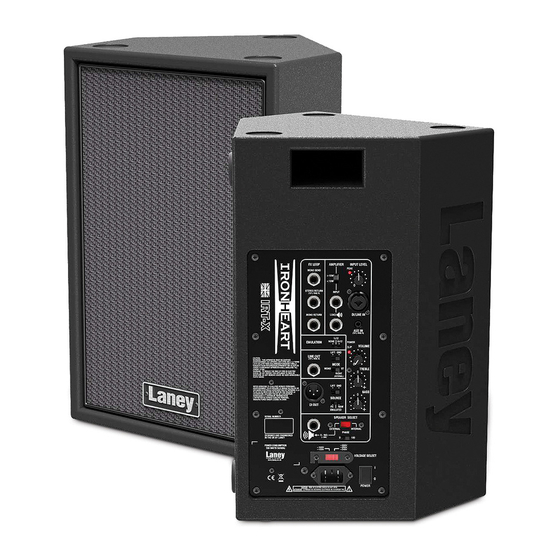
PANEL CONTROLS 1. MAINS INLET SOCKET: IEC input for connection of an appropriate mains lead. Make sure the voltage indicated on the voltage selection switch is correct for your country! 2. MAINS SWITCH: Turns the system on and off. Ensure the level controls are at minimum when switching on and off. -
Page 10: Setup Options
SET UP OPTIONS Connection Options 1. Remove the internal speaker jack from the rear panel of your amplifier, connect a lead from the IRT-X Input Socket to the internal speaker socket on your amplifier. Connect a lead from the Load Socket on the IRT-X to your internal speaker lead. 2. - Page 15 This device may not cause harmful interference This device must accept any interference received, that may cause undesired operation. Warning: Changes or modification to the equipment not approved by Laney can void the user's authority to use the equipment. Note: This equipment has been tested and found to comply with the limits for Class B digital device, pursuant to Part 15 of the FCC Rules.
- Page 16 Power Requirements: ~115V (~85V-132V) & ~230V (~170V-264V)(User selectable via panel switch) Typical power consumption: 100W at 50-60Hz. Amplifier power output: 200W into 4R @1%THD. Amplifier topology: High performance Class D with SMPS. Loudspeakers: 1x8” Custom high power bass driver. 1” compression driver tweeter. Crossover: 2 way passive with tweeter protection.
-
Page 17: Block Diagram
BLOCK DIAGRAM LINE DIRECT SOURCE DIRECT EMULATED DIRECT OUT COMBI INPUT INPUT LEVEL Peak LIFT Ʃ EMLATION EMULATION BYPASS 1 X 12 INSERT SEND 4 X 12 ATTENUATION >10W <10W AMPLIFIER INPUT INTERNAL HF DRIVER LOAD OUT 200W CLASS D POWER AMPLIFIER SPEAKER SELECT PASSIVE... - Page 18 WARNING: When using electrical products, basic cautions should always be followed, including the following: 1. Read these instructions. 2. Keep these instructions safe. 3. Heed all warnings. 4. Follow all instructions. 5. Do not use this apparatus near water. 6. Clean only with a dry cloth. 7.
- Page 20 OPERATING INSTRUCTIONS - ISSUE 1.2...
Need help?
Do you have a question about the Iron heart and is the answer not in the manual?
Questions and answers