Advertisement
Table of Contents
Advertisement
Table of Contents

Related Manuals for ALLEN & HEATH XB-14


Summary of Contents for ALLEN & HEATH XB-14
- Page 1 XB-14 Quick Operation Manual V1 23/10/2013...
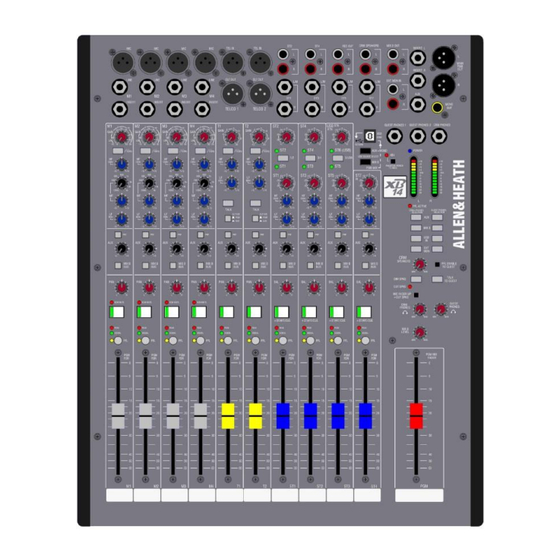
- Page 2 MIXER ON/OFF SWITCH GAIN CONTROL ST16 SELECTOR SELECTOR GAIN CONTROL 100Hz HIGH MAIN PASS FILTER GAIN METERS PHANTOM CONTROL POWER SPEAKERS GUEST PHONES SWITCH FADER UP PHONES FADER MIC 2 PGM OUT MIC 1 PLAY-OUT Page 2 of 6...
- Page 3 2. Switch on the 2 Speakers on your left and right. Ensure that the speakers volume knob is turned to the right at least 75%. 3. Switch on the XB-14 Radio Mixer (14). 4. Make sure you are logged in to AVID server. (Nothing should be saved on the Radio Lab computers) Warning! To protect your hearing do not operate the headphones or sound system at excessively high volume.
- Page 4 Ensure that the levels you see on the board when you are talking are at least one forth (1/4) of the scale in the MAIN METERS (13). If not adjust the Gain Knob at the top of the strip (7). xii.
- Page 5 Terminology Mic Input Socket Standard 3-Pin XLR socket wired as Pin 1=Chassis, Pin 2=hot (+), Pin 3=Cold (-). Gain Control This adjusts the gain of the input amplifier to match the signal level of the input. The gain is varied from –6dB attenuation) to +63dB for signals plugged in to the xlr socket (Mic Input) and –10dB to +26dB for signals plugged into the Line input jack.
- Page 6 Guest Phones level Adjusts the level of the guests’ headphones from off (fully attenuated) to maximum. Each headphone output socket has a dedicated amplifier with a gain of 12dB. Program Mix Fader The main program mix level control. Affects the stereo PGM output, but not the mono PGM output. 0dB, or unity gain is at the t op of the fader.
Need help?
Do you have a question about the XB-14 and is the answer not in the manual?
Questions and answers