Table of Contents
Advertisement
Quick Links
Advertisement
Table of Contents

Related Manuals for ASROCK Rack EPC602D8A


Summary of Contents for ASROCK Rack EPC602D8A
-
Page 2: Copyright Notice
In no event shall ASRock Rack, its directors, oicers, employees, or agents be liable for any indirect, special, incidental, or consequential damages (including damages for loss of proits, loss of business, loss of data, interruption of business and the like), even if ASRock Rack has been advised of the possibility of such damages arising from any defect or error in the documentation or product. - Page 3 Contact Information If you need to contact ASRock Rack or want to know more about ASRock Rack, you’re welcome to visit ASRock Rack’s website at www.ASRockRack.com; or you may contact your dealer for further information. ASRock Rack Incorporation 6F., No.37, Sec. 2, Jhongyang S. Rd., Beitou District,...
-
Page 4: Table Of Contents
Contents Chapter 1 Introduction 1.1 Package Contents 1.2 Speciications 1.3 Unique Features 1.4 Motherboard Layout 1.5 I/O Panel 1.6 Block Diagram Chapter 2 Installation 2.1 Screw Holes 2.2 Pre-installation Precautions 2.3 Installing the CPU 2.4 Installing the CPU Fan and Heatsink 2.5 Installation of Memory Modules (DIMM) 2.6 Expansion Slots (PCI and PCI Express Slots) 2.7 Jumper Setup... - Page 5 3.1.2 Navigation Keys 3.2 Main Screen 3.3 OC Tweaker Screen 3.3.1 CPU Coniguration 3.3.2 DRAM Timing Coniguration 3.3.3 Voltage Coniguration 3.3.4 Saving Current Settings as User Defaults 3.4 Advanced Screen 3.4.1 Easy RAID Installer 3.4.2 ACPI Coniguration 3.4.3 Intel TXT(LT-SX) Coniguration 3.4.4 WHEA Coniguration 3.4.5 CPU Coniguration 3.4.6 North Bridge Coniguration...
- Page 6 3.8 Security Screen 3.9 Exit Screen 3.10 Event Logs Chapter 4 Software Support 4.1 Install Operating System 4.2 Support CD Information 4.2.1 Running The Support CD 4.2.2 Drivers Menu 4.2.3 Utilities Menu 4.2.4 Contact Information Chapter 5 Troubleshooting 5.1 Troubleshooting Procedures 5.2 Technical Support Procedures 5.3 Returning Merchandise for Service...
-
Page 7: Chapter 1 Introduction
In case any modiications of this manual occur, the updated version will be available on ASRock Rack website without further notice. You may ind the latest memory and CPU support lists on ASRock Rack website as well. ASRock Rack’s Website: www.ASRockRack.com If you require technical support related to this motherboard, please visit our website for speciic information about the model you are using. -
Page 8: Speciications
1.2 Speciications EPC602D8A / EPC602D8A-V+ MB Physical Status Form Factor Dimension 12'' x 9.6'' (30.5 cm x 24.4 cm) Processor System - Intel® Xeon processor E5-1600/2600/4600 & v2 series - Supports Hyper-hreading Technology Socket Single Socket R (LGA2011) Chipset Intel® C602... - Page 9 EPC602D8A / EPC602D8A-V+ Management BMC Controller For EPC602D8A only: ASPEED AST2300 For EPC602D8A-V+ only: IPMI Dedicated For EPC602D8A Only: GLAN 1 x Realtek RTL8211E for dedicated management GLAN For EPC602D8A-V+ Only: Features - Watch Dog - NMI Gracphics Controller For EPC602D8A only:...
- Page 10 BIOS Features - Plug and Play (PnP) - ACPI 1.1 Compliance Wake Up Events - SMBIOS 2.3.1 Support - DRAM Voltage Multi-adjustment - ASRock Instant Flash Hardware Monitor Temperature - CPU Temperature Sensing - System Temperature Sensing - CPU/Rear/Front Fan Tachometer...
- Page 11 EPC602D8A / EPC602D8A-V+ Support OS Microsot® Windows® - Windows 7 ( 32 / 64 bit) - Windows 8 ( 32 / 64 bit) - Windows 8.1 ( 32 / 64 bit) - Server 2008 R2 (64 bit) - Server 2012 (64 bit) - Server 2012 R2 (64 bit) Linux®...
-
Page 12: Unique Features
. With this utility, you can press the <F6> key during the POST or the <F2> key to enter into the BIOS setup menu to access ASRock Rack Instant Flash. Just launch this tool and save the new BIOS ile to your USB lash drive, loppy disk or hard drive, then you can update your BIOS only in a few clicks without preparing an additional loppy diskette or other complicated lash utility. -
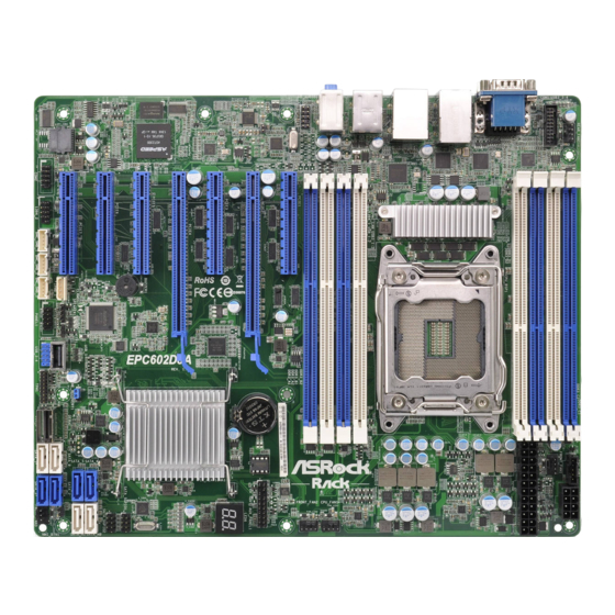
Page 13: Motherboard Layout
EPC602D8A / EPC602D8A-V+ 1.4 Motherboard Layout EPC602D8A 24.4cm (9.6 in) DDR3_C1 (64 bit, 240-pin module) REAR_FAN1 PSU_SMB1 ATX12V1 DDR3_C2 (64 bit, 240-pin module) FRNT_FAN1 USB3_3_4 DDR3_D1 (64 bit, 240-pin module) ATXPWR1 DDR3_D2 (64 bit, 240-pin module) LAN2 LAN1 USB 3.0... - Page 14 EPC602D8A-V+ 24.4cm (9.6 in) REAR_FAN1 DDR3_C1 (64 bit, 240-pin module) PSU_SMB1 ATX12V1 DDR3_C2 (64 bit, 240-pin module) FRNT_FAN1 USB3_3_4 DDR3_D1 (64 bit, 240-pin module) ATXPWR1 DDR3_D2 (64 bit, 240-pin module) LAN2 LAN1 USB 3.0 T: USB3_2 B: USB3_1 USB 2.0...
- Page 15 EPC602D8A / EPC602D8A-V+ Description Rear Fan Connector (REAR_FAN1) USB 3.0 Header (USB3_3_4) 2 x 240-pin DDR3 DIMM Slots (DDR3_C2, DDR3_D2, White) 2 x 240-pin DDR3 DIMM Slots (DDR3_C1, DDR3_D1, Blue) PSU SMBus (PSU_SMB1) ATX 12V Power Connector (ATX12V1) Front Fan Connector (FRONT_FAN1)
- Page 16 Description BMC SMBus Header (BMC_SMB_1) IEEE 1394 Header (1394_2) COM Port Header (COM2) Intelligent Platform Management Bus header (IPMB_1) Vertical Type A USB 2.0 (USB_5) ME Recovery Jumper (ME_RECOVERY1) HDMI_SPDIF Header (HDMI_SPDIF1) Front Panel Audio Header (HD_AUDIO1)
-
Page 17: I/O Panel
EPC602D8A / EPC602D8A-V+ 1.5 I/O Panel EPC602D8A No. Description No. Description Serial Port (COM1) IEEE 1394 Port (LAN2) VGA Port (VGA1) USB 2.0 Ports (USB_1-2) LAN RJ-45 Port (LAN2)* Line In (Light Blue) LAN RJ-45 Port (LAN1)* Front Speaker (Lime) - Page 18 LAN Port LED Indications *here are two LED next to the LAN port. Please refer to the table below for the LAN port LED indications. ACT/LINK LED SPEED LED LAN Port Dedicated IPMI LAN Port LED Indications Activity / Link LED Speed LED Status Description...
-
Page 19: Block Diagram
PCIEx16 Slot1 : PCI-E GEN3 x8 Slot(EE : x0/x8 with Slot2) Quad-Channel Memory x8 Slots CH A DDR3 1066/1333/1600 Slot2 : PCI-E GEN3 x16 Slot(EE : x16/x8 with Slot1) Intel Processor Sandy Bridge-E PCIEx16 Slot3 : PCI-E GEN3 x8 Slot(EE : x0/x8 with Slot4) DDR3 1066/1333/1600 CH B Ivy Bridge-E... -
Page 20: Chapter 2 Installation
Chapter 2 Installation his is an ATX form factor (12'' x 9.6'', 30.5 cm x 24.4 cm) motherboard. Before you install the motherboard, study the coniguration of your chassis to ensure that the motherboard its into it. Make sure to unplug the power cord before installing or removing the motherboard. Failure to do so may cause physical injuries to you and damages to motherboard components. -
Page 21: Pre-Installation Precautions
EPC602D8A / EPC602D8A-V+ 2.2 Pre-installation Precautions Take note of the following precautions before you install motherboard components or change any motherboard settings. 1. Unplug the power cord from the wall socket before touching any components. 2. To avoid damaging the motherboard’s components due to static electricity, NEVER place your motherboard directly on the carpet or the like. -
Page 22: Installing The Cpu
2.3 Installing the CPU... - Page 23 EPC602D8A / EPC602D8A-V+...
- Page 24 he cover must be placed if returning the motherboard for ater service.
-
Page 25: Installing The Cpu Fan And Heatsink
EPC602D8A / EPC602D8A-V+ 2.4 Installing the CPU Fan and Heatsink 1. Before you installed the heatsink, you need to spray thermal interface material between the CPU and the heatsink to improve heat dissipation. 2. Be sure to use a CPU fan for narrow ILM socket. -
Page 26: Dual Channel Memory Coniguration
2.5 Installation of Memory Modules (DIMM) his motherboard provides eight 240-pin DDR3 (Double Data Rate 3) DIMM slots, and supports Dual Channel Memory Technology. 1. For dual channel coniguration, you always need to install identical (the same brand, speed, size and chip-type) DDR3 DIMM pairs. 2. - Page 27 EPC602D8A / EPC602D8A-V+...
-
Page 28: Expansion Slots (Pci And Pci Express Slots)
2.6 Expansion Slots (PCI and PCI Express Slots) here are 7 PCI Express slots on this motherboard. PCIE slot: PCIE7 (PCIE 2.0 x8 slot, from Intel C602 chipset) is used for PCI Express x2 lane width graphics cards. PCIE1, PCIE3, PCIE5 and PCIE6 (PCIE 3.0 x8 slot, from CPU) are used for PCI Express x8 lane width graphics cards. -
Page 29: Installing An Expansion Card
EPC602D8A / EPC602D8A-V+ Installing an expansion card Step 1. Before installing an expansion card, please make sure that the power supply is switched of or the power cord is unplugged. Please read the documentation of the expansion card and make necessary hardware settings for the card before you start the installation. -
Page 30: Jumper Setup
2.7 Jumper Setup he illustration shows how jumpers are setup. When the jumper cap is placed on the pins, the jumper is “Short”. If no jumper cap is placed on the pins, the jumper is “Open”. he illustration shows a 3-pin jumper whose pin1 and pin2 are “Short” when a jumper cap is placed on these 2 pins. -
Page 31: Onboard Headers And Connectors
EPC602D8A / EPC602D8A-V+ 2.8 Onboard Headers and Connectors Onboard headers and connectors are NOT jumpers. Do NOT place jumper caps over these headers and connectors. Placing jumper caps over the headers and connectors will cause permanent damage to the motherboard. - Page 32 Auxiliary Panel Header his header supports multiple (18-pin AUX PANEL_1) functions on the front panel, (see p.7, No. 13) including the front panel SMB, internet status indicator and chassis intrusion pin. A. Front panel SMBus connecting pin (6-1 pin FPSMB) his header allows you to connect SMBus (System Management Bus) equipment.
- Page 33 EPC602D8A / EPC602D8A-V+ Serial ATA3 Connectors hese four SATA3 connectors SATA_M0 (SATA_M0) support SATA data cables for SATA_M1 (see p.7, No. 17) internal storage devices with (SATA_M1) up to 6.0 Gb/s data transfer SATA_0 (see p.7, No. 18) rate. SATA_1 (SATA_0) (see p.7, No.
- Page 34 PRESENCE# Front Panel Audio Header his is an interface for the MIC_RET (9-pin HD_AUDIO1) front panel audio cable that OUT_RET (see p.7, No. 41) allows convenient connection and control of audio devices. OUT2_L J_SENSE OUT2_R MIC2_R MIC2_L 1. High Deinition Audio supports Jack Sensing, but the panel wire on the chassis must support HDA to function correctly.
- Page 35 EPC602D8A / EPC602D8A-V+ CPU Fan Connector his motherboard provides GN D (4-pin CPU_FAN1) a 4-Pin CPU fan (Quiet Fan) + 12V (see p.7, No. 10) connector. If you plan to CPU_ FAN_SPEED FAN_SPEED_CONTROL connect a 3-Pin CPU fan, please connect it to Pin 1-3.
- Page 36 RRXD1 Serial Port Header his COM2 header supports DDTR#1 (9-pin COM2) a serial port module. DDSR#1 CCTS#1 (see p.7, No. 36) RRI#1 RRTS#1 TTXD1 DDCD#1 TPM Header his connector supports (17-pin TPM1) Trusted Platform Module (see p.7, No. 27) (TPM) system, which can securely store keys, digital certiicates, passwords, and data.
- Page 37 EPC602D8A / EPC602D8A-V+ Intelligent Platform No connect This 4-pin connector is used Management Bus header to provide a cabled base-board (4-pin IPMB_1) or front panel connection for IPMB_SCL (see p.7, No. 37) value added features and 3rd- IPMB_SDA party add-in cards, such as...
-
Page 38: Dr. Debug
2.9 Dr. Debug Dr. Debug is used to provide code information, which makes troubleshooting even easier. Please see the diagrams below for reading the Dr. Debug codes. Code Description Please check if the CPU is installed correctly and then clear CMOS. Problem related to memory, VGA card or other devices. -
Page 39: Driver Installation Guide
EPC602D8A / EPC602D8A-V+ 2.10 Driver Installation Guide To install the drivers to your system, please insert the support CD to your optical drive irst. hen, the drivers compatible to your system can be auto-detected and listed on the support CD driver page. Please follow the order from top to bottom to install... -
Page 40: Dual Lan And Teaming Operation Guide
2.11 Dual LAN and Teaming Operation Guide Dual LAN with Teaming enabled on this motherboard allows two single connections to act as one single connection for twice the transmission bandwidth, making data transmission more efective and improving the quality of transmission of distant images. -
Page 41: Chapter 3 Uefi Setup Utility
To set up the advanced UEFI features H/W Monitor To display current hardware status Server Mgmt To manage the server (not supported for EPC602D8A-V+) To set up the default system device to locate and load the Boot Operating System Security... -
Page 42: Navigation Keys
3.1.2 Navigation Keys Please check the following table for the function description of each navigation key. Navigation Key(s) Function Description Moves cursor let or right to select Screens Moves cursor up or down to select items + / - To change option for the selected items <Tab>... -
Page 43: Main Screen
EPC602D8A / EPC602D8A-V+ 3.2 Main Screen Once you enter the UEFI SETUP UTILITY, the Main screen will appear and display the system overview. he Main screen provides system overview information and allows you to set the system time and date. -
Page 44: Oc Tweaker Screen
3.3 OC Tweaker Screen In the OC Tweaker screen, you can set up overclocking features. 3.3.1 CPU Coniguration CPU Ratio Setting Use this item to adjust the Core Ratio. he CPU speed is determined by the CPU Ratio multiplied with the BCLK. Increasing the CPU Ratio will increase the internal CPU clock speed without afecting the clock speed of other components. -
Page 45: Dram Timing Coniguration
EPC602D8A / EPC602D8A-V+ Intel SpeedStep Technology Intel SpeedStep technology is Intel’s new power saving technology. Processors can switch between multiple frequencies and voltage points to enable power saving. he default value is [Enabled]. Configuration options: [Enabled] and [Disabled]. If you install Windows®... -
Page 46: Voltage Coniguration
assign the appropriate frequency automatically. 3.3.3 Voltage Coniguration CPU Load-Line Calibration CPU Load-Line Calibration helps prevent CPU voltage droop when the system is under heavy load. CPU Core Voltage Use this to select CPU Core Voltage. he default value is [Auto]. VCCSA Voltage Use this to select VCCSA Voltage. -
Page 47: Advanced Screen
EPC602D8A / EPC602D8A-V+ 3.4 Advanced Screen In this section, you may set the conigurations for the following items: Easy RAID Install- er, ACPI Configuration, Intel TXT(LS-SX) Configuration, WHEA Configuration, CPU Coniguration, North Bridge Coniguration, South Bridge Coniguration, USB Conigura- tion, ME Subsystem, Clock Generator Configuration, Storage Configuration, Super IO Coniguration, Serial Port Console Redirection, Voltage Control and Instant Flash. -
Page 48: Easy Raid Installer
3.4.1 Easy RAID Installer Easy RAID Installer can help you to copy the RAID driver from a support CD to your USB storage device. Ater copying the RAID driver to your USB storage device, please change “SATA Mode” to “RAID”, then you can start installing the OS in RAID mode. -
Page 49: Acpi Coniguration
EPC602D8A / EPC602D8A-V+ 3.4.2 ACPI Coniguration Check Ready Bit Use this item to enable or disable the feature Check Ready Bit. Suspend to RAM Use this item to select whether to auto-detect or disable the Suspend-to-RAM feature. Se- lecting [Auto] will enable this feature if the OS supports it. -
Page 50: Intel Txt(Lt-Sx) Coniguration
Ring-In Power On Use this item to enable or disable Ring-In signals to turn on the system from the power- sot-of mode. USB Keyboard/Remote Power On Use this item to enable or disable USB Keyboard/Remote to turn on the system from the power-sot-of mode. -
Page 51: Whea Coniguration
EPC602D8A / EPC602D8A-V+ 3.4.4 WHEA Coniguration WHEA Support Use this option to enable or disable Windows Hardware Error Architecture. he default value is [Enabled]. -
Page 52: Cpu Coniguration
3.4.5 CPU Coniguration CPU_BSP1 Information Display information regarding the primary processor (BootStrap Processor). Intel Hyper Threading Technology Intel Hyper hreading Technology allows multiple threads to run on each core, so that the overall performance on threaded sotware is improved. Active Processor Cores Select the number of cores to enable in each processor package. -
Page 53: Intel Virtualization Technology
EPC602D8A / EPC602D8A-V+ Adjacent Cache Line Prefetch Automatically prefetch the subsequent cache line while retrieving the currently requested cache line. Enable for better performance. DCU Streamer Prefetcher If enabled, the DCU (data cache unit) Streamer Prefetcher prefetches the next L1 Data line based upon multiple loads in same cache line. -
Page 54: North Bridge Coniguration
Short Duration Power Limited Use this item to conigure short duration power limit in watts. If 0 is selected, the option will turn to [Auto]. 3.4.6 North Bridge Coniguration IOH Coniguration Intel(R) VT-d Use this item to enable or disable Intel(R) Virtualization Technology for Directed I/O. he default value is [Disabled]. -
Page 55: Memory Coniguration
EPC602D8A / EPC602D8A-V+ PCIE 1 & PCIE 2 Link Width his allows you to select PCIE 1 & PCIE 2 Link Width. he default value is [Gen2]. PCIE 1 & PCIE 2 Link Speed his allows you to select PCIE1 & PCIE2 Link Speed. he default value is [Auto]. -
Page 56: Channel Interleaving
Perform and DFX Devices his item can set the Perform and DFX devices hidden or unhidden. DRAM RAPL(Running Average Power Limit ) Mode RAPL (Running Average Power Limit ) provides mechanisms to enforce power consumption limits on supported processors. he default is [DRAM RAPL Mode 1]. DRAM Frequency If [Auto] is selected, the motherboard will detect the memory module(s) inserted and assigns appropriate frequency automatically. -
Page 57: Deep Sleep
EPC602D8A / EPC602D8A-V+ 3.4.7 South Bridge Coniguration Restore on AC/Power Loss his allows you to set the power state ater an unexpected AC/power loss. If [Power Of] is selected, the AC/power remains of when the power recovers. If [Power On] is selected, the AC/power resumes and the system starts to boot up when the power recovers. - Page 58 Onboard Debug Port LED Use this to enable or disable the Onboard Debug Port LED. he default value is [Auto]. Onboard HD Audio Select [Enabled], [Disabled] or [Auto] for the onboard HD Audio feature. If you select [Enabled], the onboard HD Audio will be disabled when PCI Sound Card is plugged. Front Panel Select [Auto] or [Disabled] for the onboard HD Audio Front Panel.
-
Page 59: Usb Coniguration
EPC602D8A / EPC602D8A-V+ 3.4.8 USB Coniguration USB 3.0 Controller Use this item to enable or disable the use of USB controller. he default value is [Enabled]. USB 2.0 Controller Use this item to enable or disable the use of USB controller. he default value is [Enabled]. -
Page 60: Me Subsystem
3.4.9 ME Subsystem ME Subsystem screen displays the Intel ME Subsystem Configuration information, such as ME Version and ME FW State. -
Page 61: Clock Generator Coniguration
EPC602D8A / EPC602D8A-V+ 3.4.10 Clock Generator Coniguration Spread Spectrum Use this item to enable or disable the spread spectrum feature. he default valu is [Disabled]. -
Page 62: Storage Coniguration
3.4.11 Storage Coniguration SATA Mode Selection Use this to select SATA mode. Configuration options: [Disabled], [IDE Mode], [AHCI Mode] and [RAID Mode]. he default value is [AHCI Mode]. AHCI (Advanced Host Controller Interface) supports NCQ and other new features that will improve SATA disk performance but IDE mode does not have these advantages. - Page 63 EPC602D8A / EPC602D8A-V+ Bootable Marvell SATA3 Controller Use this to enable or disable Onboard Marvell SATA3 Option ROM. If Option ROM is disabled, you cannot use the SATA devices connected to the Marvell SATA3 controller as Boot Device. SCU Devices Use this to enable or disable SCU devices.
-
Page 64: Super Io Coniguration
3.4.12 Super IO Coniguration Serial Port 1 Coniguration Use this item to conigure the onboard serial port 1. Select and enter the "Serial Port 1 Coniguration" and you will see the followings: Serial Port Use this item to enable or disable the onboard serial port. Change Settings Use this item to select an optimal setting for Super IO device. -
Page 65: Serial Port Console Redirection
EPC602D8A / EPC602D8A-V+ 3.4.13 Serial Port Console Redirection Console Redirection Use this option to enable or disable Console Redirection. If this item is set to Enabled, you can select a COM Port to be used for Console Redirection. Console Redirection Settings Use this option to conigure Console Redirection Settings, and specify how your computer and the host computer to which you are connected exchange information. -
Page 66: Flow Control
Bits Per Second Use this item to select the serial port transmission speed. The speed used in the host computer and the client computer must be the same. Long or noisy lines may require lower transmission speed. he options include [9600], [19200], [57600] and [115200]. Data Bits Use this item to set the data transmission size. -
Page 67: Voltage Control
EPC602D8A / EPC602D8A-V+ 3.4.14 Voltage Control CPU Load-Line Calibration CPU Load-Line Calibration helps prevent CPU voltage droop when thesystem is under heavy load. CPU Core Voltage Use this to select CPU Core Voltage. he default value is [Auto]. VCCSA Voltage Use this to select VCCSA Voltage. -
Page 68: Instant Flash
3.4.15 Instant Flash Instant Flash is a UEFI lash utility embedded in Flash ROM. his convenient UEFI update tool allows you to update system UEFI without entering operating systems ® irst like MS-DOS or Windows . Just save the new UEFI ile to your USB lash drive, loppy disk or hard drive and launch this tool, then you can update your UEFI only in a few clicks without preparing an additional loppy diskette or other compli- cated lash utility. -
Page 69: H/W Monitor Screen (Hardware Health Event Monitoring)
EPC602D8A / EPC602D8A-V+ 3.5 H/W Monitor Screen (Hardware Health Event Monitoring) In this section, it allows you to monitor the status of the hardware on your system, includ- ing the parameters of the CPU temperature, motherboard temperature, CPU fan speed, chassis fan speed, and the critical voltage. -
Page 70: Watch Dog Timer
Smart Fan Control his allows you to set the Smart fan’s level speed. Smart Fan Duty Control Smart Fan Duty x (x means 1 to 11 stage) his allows you to set duty cycle for each stage. Smart Fan Temp Control Smart Fan Temp x (x means 1 to 11 stage) his allows you to set temperature for each stage. -
Page 71: Server Mgmt (Server Management)
EPC602D8A / EPC602D8A-V+ 3.6 Server Mgmt (Server Management) System Event Log Enter to conigure System Event Logging features during boot. BMC Network Coniguration Enter to conigure BMC Network parameters. Coniguration Address Source Select to conigure BMC network parameters statically or dynamically(by BIOS or BMC). -
Page 72: Boot Screen
3.7 Boot Screen In this section, it will display the available devices on your system for you to conigure the boot settings and the boot priority. Boot Option Priorities- Boot Option #1 Use this item to set the system boot order. Setup Prompt Timeout his shows the number of seconds to wait for setup activation key. - Page 73 EPC602D8A / EPC602D8A-V+ AddOn ROM Display Use this option to adjust AddOn ROM Display. If you enable the option “Full Screen Logo” but you want to see the AddOn ROM information when the system boots, please select [Enabled]. Coniguration options: [Enabled] and [Disabled]. he default value is [Enabled].
-
Page 74: Security Screen
3.8 Security Screen In this section, you may set or change the supervisor/user password for the system. For the user password, you may also clear it. Supervisor Password Set or change the password for the administrator account. Only the administrator has authority to change the settings in the UEFI Setup Utility. -
Page 75: Exit Screen
EPC602D8A / EPC602D8A-V+ 3.9 Exit Screen Save Changes and Exit When you select this option, the following message “Save coniguration changes and exit setup?” will pop-out. Select [Yes] to save the changes and exit the UEFI SETUP UTILITY. Discard Changes and Exit When you select this option, the following message “Discard changes and exit setup?”... -
Page 76: Event Logs
3.10 Event Logs Change Smbios Event Log Settings his allows you to conigure the Smbios Event Log Settings. When entering the item, you will see the followings: Smbios Event Log Use this item to enable or disable all features of the SMBIOS Event Logging during system boot. - Page 77 EPC602D8A / EPC602D8A-V+ entries which utilize a multiple-event counter. he value ranges from 0 to 99 minutes. View Smbios Event Log his allows you to view the Smbios Event Log records. All values changed here do not take efect until computer is restarted.
-
Page 78: Chapter 4 Software Support
4.2.4 Contact Information If you need to contact ASRock Rack or want to know more about ASRock Rack, welcome to visit ASRock Rack’s website at http://www.ASRockRack.com; or you may contact your... -
Page 79: Chapter 5 Troubleshooting
EPC602D8A / EPC602D8A-V+ Chapter 5 Troubleshooting 5.1 Troubleshooting Procedures Follow the procedures below to troubleshoot your system. Always unplug the power cord before adding, removing or changing any hardware com- ponents. Failure to do so may cause physical injuries to you and damages to motherboard components. - Page 80 1. Verify if the battery on the motherboard provides ~3VDC. Install a new battery if it does not. 2. Conirm whether your power supply provides adaquate and stable power. Other problems... 1. Try searching keywords related to your problem on ASRock Rack’s FAQ page: http://www.asrockrack.com/support...
-
Page 81: Technical Support Procedures
P/N: 15G065009001AK V1.1 5.2 Technical Support Procedures If you have tried the troubleshooting procedures mentioned above and the problems are still unsolved, please contact ASRock Rack’s technical support with the following information: 1. Your contact information 2. Model name, BIOS version and problem type.
Need help?
Do you have a question about the Rack EPC602D8A and is the answer not in the manual?
Questions and answers